
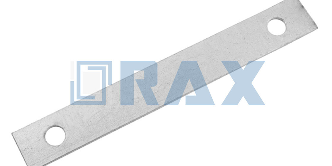
When the tailboard drops at the first pole, the whole job sits in plain view: two galvanized flat braces, machine bolts, washers, and lag screws sorted by size. Cross arm brace installation rewards that ten seconds of counting, because every fastener on the board has exactly one right hole. The brace pair is what keeps a tangent arm level under span load, and it is also the fitting that gets revisited when hardware goes up mismatched.
Loose brace hardware is not a small defect to shrug off. Journeyman rodeo rules deduct points for any hardware left unsecured, and the same defect on a live line reads as a ticking arm in the wind. The sequence below keeps that off the callback list: where each brace sits, which fastener leads, and what gets verified before anyone descends.
Lay Out the Hardware on the Tailboard
Count the parts against the print before the truck moves. A flat brace pair needs two braces, one machine bolt with nut and washers per brace, and the lag screws the construction standard calls out. Hole sizes tell you which fastener goes where, so read the steel before anything climbs.
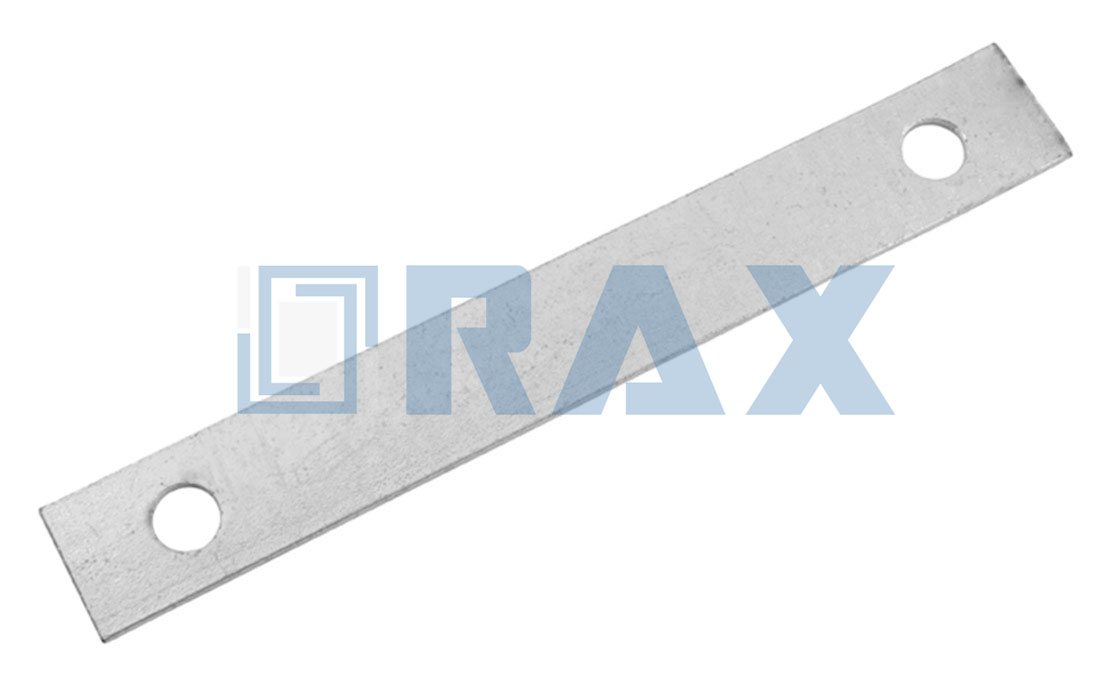
RaxPower publishes its cross arm brace with a 7/16-inch hole at the arm end and a 9/16-inch hole at the pole end, punched one inch from each rounded tip. The 7/16-inch hole takes a 3/8-inch machine bolt in the catalog pairing, where the hole runs one size over the fastener. The 9/16-inch hole clears a 1/2-inch lag screw the same way.
The tool list rides a belt without complaint.
- Wrench matched to the machine bolt nut, plus a spud wrench for lining up holes.
- Drill with the lead-hole bit sized per the utility standard for 1/2-inch lag screws.
- Carpenter level and a straightedge for reading the arm after it goes up.
- Tape measure to confirm brace length and hole spacing against the drawing.
Check the coating while you count. Hot-dip galvanizing to ISO 1461 or ASTM A123 should read uniform gray with no bare steel at the punched holes, and RaxPower braces carry a mean coating above 85 microns. A brace scuffed to bare steel in the truck bed goes back in the bin, not up the pole.
What a Cross Arm Brace Does
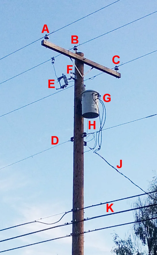
A tangent crossarm wants to tip toward the span the moment conductors take tension. Two braces run from the underside of the arm down to the pole face, one from each side, and they form a V. Together the pair turns that tipping force into compression and tension the pole handles easily. It works the way a strut pair holds a gate frame square: neither member carries the load alone.
Utility standards treat the brace as mandatory, not optional. Seattle City Light construction standard 0100.09 states that all tangent crossarms require a brace, even when the arm mounts on a two-hole bracket. The same standard exempts deadend assemblies, where the arm points back against the pull and needs no brace.
Brace style follows arm style. Brace length comes off the arm drawing rather than a one-size rule, so read the print before ordering a flat bar pair. Seattle City Light gives one verified pairing. Its standard moves an 11-foot wing arm to a single steel pipe brace, 1-1/4 inches in diameter and nine feet one inch long, with a 5/8-inch bolt.
Check the Arm and Pole Before Fitting
Bracing cannot rescue a bad member, so the inspection comes first. Sight the arm for cracks, deep weather checking, and old bolt holes that overlap the new positions. A split at the through-bolt line fails under load no matter how well the braces fit, and the only fix is a new arm.
Read the pole face next. The lag screw positions need sound wood with no decay, no old hardware, and no fire damage where the washers will seat. Then confirm the fastener schedule on the print before anyone climbs. Seattle City Light pairs its flat braces with 1/2-inch machine bolts at the arm and a 1/2-inch lag screw at the pole. That schedule assumes braces drilled for the larger bolt; the print, not a generic chart, sizes both ends.
The 11-foot wing arm pipe brace takes a 5/8-inch bolt and two 1/2-inch lag screws.
Hardware selection starts on the ground, not at the top. The pole line hardware range groups braces, plates, and bands in one place so a crew can match holes and fasteners before the climb. Matching on the tailboard beats discovering a mismatch at forty feet.
Bolt the Braces to the Arm First
Sequence is the whole craft here. Bolt each brace to the arm while the arm still lies on the ground or hangs in reach. Start the machine bolt square and leave it loose enough for the brace to swing. Lag the pole end first and the brace cannot find its angle without force.
- Lay out the brace pair on the arm underside with the rounded ends outboard.
- Pass the machine bolt through the arm face and the 7/16-inch brace hole.
- Add a washer under the head and under the nut to spread the clamp load.
- Snug the nut until the brace still swings under hand pressure, then stop.
Washers matter more at wood than at steel. Bare bolt heads crush wood fibers and the clamp load fades through the first season of wet-dry cycles. Seattle City Light specifies round washers at the flat brace bolts, and a square flat washer plus a spring lock washer where the pipe brace meets the wing arm.
Watch the bolt direction while the arm is in hand. Set practice runs the head to the side that keeps the nut reachable from the working position. Rodeo rulebooks penalize improper framing, but the through-bolt direction comes from your utility print, not a rulebook. A nut nobody can reach gets checked less.
Set the Arm and Square the Geometry
With the braces swinging free on their arm bolts, the arm goes up and the geometry gets set. Raise the arm onto the pole face, start the through-bolt, and read it level across the length before anything tightens. A quarter bubble off at this stage becomes a visible sag by the next inspection.
Sight the arm along the line direction so the pins and insulators face the span squarely. Then swing each brace up to the pole and mark the lag positions through the steel. Rodeo practice says it best: set the lag on top of the brace, but do not drive it yet. Hand-snug fasteners hold the geometry while you still have both hands to correct it.
The V should look symmetric from the ground, both braces at the same angle with equal reach. If one brace sits steeper than its partner, the arm bolt holes or the pole marks have drifted. Fix it now, because steel will not forgive a crooked start once the lags bite.
Lag the Braces to the Pole
The pole connection is where cross arm brace installation earns its holding power. Lag screws in sound wood carry the brace load for decades; lags driven carelessly back out within a season. The difference is lead holes and thread engagement, both decided before the wrench moves.
- Mark both lag centers through the 9/16-inch brace holes, square to the pole face.
- Drill lead holes where the governing standard requires them; practice varies by species.
- Start each 1/2-inch lag screw by hand so the threads catch true and square.
- Wrench the lag until the washer seats flat on the steel, not past it.
- Confirm the fastener count matches the print before moving down the pole.
Fastener counts are not interchangeable between brace styles. Seattle City Light calls one 1/2-inch lag screw per flat brace on tangent arms. The wing arm pipe brace takes two 1/2-inch lag screws, because the pipe sees different load. The print governs; when it is silent, the utility standard answers.
Length is the quiet variable. The lag must pass through the brace bar and bury full thread in the pole, which is why standards list 4-inch and 6-inch lag screws against 1/4-inch bar stock. Hold the candidate screw against the assembled brace and count the engagement before committing.
Tighten in Sequence and Verify the Work
Final tightening runs in one pass with a plan: arm bolts first, then lags, then a re-read of the geometry. Snug in stages and re-check the level, the way you would torque a wheel in a star pattern. A connection tightened all at once can pull the arm off level and lock the error in.
How tight is final? Tight to the governing specification, and no further. No universal torque figure is published for cross arm brace installation, because wood density varies pole to pole and crushed fibers lose clamp load either way. Washers flat on steel with full thread engagement is the verifiable condition.
Then verify the way judges do. Rodeo rules make crews tug on the cross-arm braces to prove the nuts are tight, and dock points when the wrong tool does the work. The same tug with a gloved hand at the pole tells you more than a glance, and a proper wrench, never adjustable pliers, is what got it there.
Fit Braces on a Double Arm Setup
Heavy tangent spans and corner structures often carry a pair of arms, one fastened to each side of the pole, tied through it. Double arming bolts do that tying. They are double-ended threaded studs in 1/2 to 3/4 inch diameters and 10 to 22 inch lengths, shipped with four square nuts, and they clamp both arms in one pull. RaxPower lists its double arming bolt in hot-dip galvanized steel to ASTM A153.
Each arm of the pair still earns its own brace work. The flat braces follow the same V pattern per arm and lag to the pole below the arm line. A double arming plate reinforces the arm ends where the bolt spacing needs backup. Both arms must read level and square together, because the pair moves as one structure under load.

Tighten a double arm symmetrically. Work bolt-for-bolt on each side so the clamp load stays balanced across the pole, then check that both arm pairs still sight level and parallel. An asymmetric tightening sequence can walk one arm out of line while the other reads true.
Safety Lines You Do Not Cross
Braces carry structure, not people. The rule needs no engineering degree behind it, only a clear line every crew repeats.
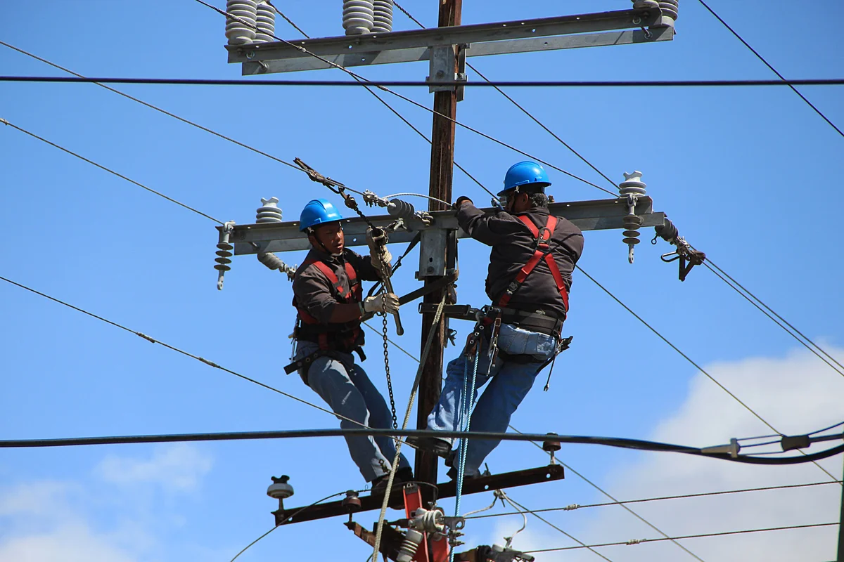
A cross arm brace is a structural support member. Never stand on one, grip it as a work position, or attach a fall-protection lanyard to it. Climbing and positioning belong to your climbing equipment and your utility's fall protection standard.
The same boundary runs through inspection habits. A brace that hums, ticks, or shows fresh movement at the lag washers gets reported, not ridden. By the time hardware announces itself audibly, the clamp load has already left the connection, and the fix is a re-torque visit, not a wait.
Handover Checklist for the Next Crew
The job ends when the next crew could arrive and trust it on sight. Run this list from the ground after the last wrench stroke, and again on the first patrol after energization.
- Every brace nut and lag washer takes a tug without movement or tick.
- Washers sit flat on the steel with no crushed wood shadow beneath.
- The arm reads level across its length and square to the span direction.
- Both braces mirror each other in angle and reach, V symmetric from grade.
- Fastener counts and sizes match the print, and the print goes into the record.
- Galvanizing shows intact at every bolt hole with no bare steel showing.
Cross arm brace installation leaves behind a quiet fitting when the sequence held: hardware matched to holes, geometry locked in the right order, and tightness proven rather than assumed. In our experience, the crews that close out with a checklist spend their patrol season listening to something other than hardware.
Cross Arm Brace Installation Questions Answered
How many braces does a tangent crossarm need?
Two steel flat braces set in a V configuration. Seattle City Light standard 0100.09 requires a brace on every tangent crossarm, even when the arm mounts on a two-hole bracket.
What size lag screws hold a brace to the pole?
Half-inch lag screws are the standard callout. Seattle City Light pairs flat braces with a 1/2-inch lag screw at the pole, and its wing-arm pipe brace takes two 1/2-inch lag screws.
Which bolt fastens the brace to the crossarm?
A machine bolt through the side of the arm, with washers under head and nut. Seattle City Light calls 1/2-inch bolts for flat braces and a 5/8-inch bolt for the 11-foot wing-arm pipe brace.
Can braces be used for climbing or fall protection?
No. Cross arm braces are structural support members only. Never use one as a climbing step, work position, or fall-protection anchor; positioning belongs to your fall protection equipment.
How tight should cross arm brace hardware be?
Snug the connections, confirm the geometry, then tighten fully with a proper wrench. No universal torque figure is published for cross arm brace installation, so the governing utility standard and brace drawing decide.
Cross Arm Brace Installation: Key Facts at a Glance
- Configuration: two steel flat braces in a V on tangent arms; one 1-1/4 inch pipe brace on 11-foot wing arms.
- Arm connection: machine bolt with washers; Seattle City Light calls 1/2-inch bolts on flat braces, 5/8-inch on the pipe brace.
- Pole connection: 1/2-inch lag screws, one per flat brace and two for the pipe brace, through 9/16-inch holes.
- RaxPower flat braces: 1-1/4 x 1/4 inch steel, 20 to 32 inches long, hot-dip galvanized to ISO 1461 or ASTM A123.
- Torque: no published universal figure; washers flat on steel and full thread engagement are the verifiable conditions.
- Prohibition: braces are structural members only, never climbing steps or fall-protection anchors.