
Imagine the crew at the first pole of a new route. The anchoring clamp that dead-ends the cable gets all the attention, and it is only half the story. Every newton of line tension flows through the clamp’s bail into a bracket, and the bracket hands the whole load to the pole. That makes the anchoring clamp pole bracket the quiet load-bearing interface of every dead end. It also makes the way you fix the bracket to the pole the real decision on this job.
RaxPower has built pole line hardware since 2003, for overhead distribution and telecom networks alike. The mounting data below comes from the bracket datasheet, plus the field questions that our production and engineering staff hear from crews and contractors. Both sources point the same way: one bracket body serves several pole types, and the attachment method is what changes.
- Why the Bracket-to-Pole Joint Decides the Dead End
- Two Ways to Put a Bracket on a Pole
- Banding: Mounting a Bracket Without Drilling
- Bolt Mounting: The Fixed Joint on Wood Poles
- Choosing Between Bands and Bolts Job by Job
- Position and Load Direction at the Pole
- What a Finished Mount Must Show Before You Leave
- Match the Mount to the Pole in Front of You
- Frequently Asked Questions About Mounting a Pole Bracket
Why the Bracket-to-Pole Joint Decides the Dead End
Follow the load path and the logic shows up. Cable tension enters the clamp’s wedge, the wedge loads the housing, the housing hangs on its bail, and the bail rests in the bracket. From there the load has one exit: the joint between bracket and pole. A bracket can match the clamp’s rating on paper and still let the dead end down if the joint around it creeps.
The datasheet numbers are modest, and that is typical for this duty. The universal pole bracket weighs 0.2 kg, measures 120 x 114 x 46 mm, and carries a mechanical strength of 200 to 930 daN depending on configuration. Its working load is 5 kN or better. Five attachment holes let the bail, a running-out roller, or a stay-off take several positions on one body.
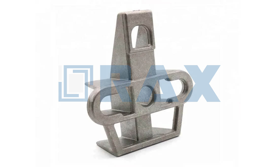
Treat the joint the way you treat a chain. The rating holds only while every link holds, and the link you make on site is the one most likely to be the weak one. That is why mounting deserves its own decision rather than a footnote in the clamp instructions.
Material helps the joint as well. The body is high-strength aluminum alloy, so the bracket resists corrosion and weighs 0.2 kg, which keeps one-handed mounting at height realistic. SGS load testing and ISO 9001 certified production stand behind the figures on the datasheet.
Two Ways to Put a Bracket on a Pole
Open the anchoring clamp pole bracket datasheet and the mounting section offers exactly two routes. The universal pole bracket page lists both for the same body. Route one uses two 20 x 0.7 mm bands with buckles, wrapped around the pole and tensioned with a hand tool. Route two uses a 14 or 16 mm bolt through the center hole, sized so the bolt is at least the pole diameter plus 50 mm long.
The two routes split the poles on any network cleanly. Wood takes a drilled, bolted joint without complaint. Concrete and steel resist drilling or forbid it, which is the exact problem the bands solve. Everything else in this guide is detail on that split.
Both routes live on the same body. The bracket carries slots that accept the flat bands plus a center hole that accepts the bolt, so the method choice adds no new parts beyond buckles or a bolt. A crew can standardize on one bracket across a mixed network and let each pole order its own fixing.
Keeping one body for both routes also simplifies the order. A distributor stocks a single bracket SKU across a mixed network, and each project sheet picks the fixing line: bands with buckles for concrete and steel, bolts for wood.
Banding: Mounting a Bracket Without Drilling
Banding turns an undrilled pole into a mounting surface. The datasheet calls for two bands, one above and one below the bracket body, each 20 mm wide and 0.7 mm thick, and each closed with a buckle.
The sequence per band takes minutes. Slide the buckle onto the band, wrap the band around the pole through the bracket’s band slots, and thread the tail through the buckle. Tension the band with a hand tool until the strap sits tight against the pole face. Lock the buckle, cut the tail flush, and repeat for the second band.
Three situations belong to this route. Concrete poles rarely offer cast holes where you need them, and field drilling spun concrete is a compromise at best. Steel and tubular poles lose their protective coating under a drill bit. And any attachment that must stay reversible starts with bands, because removal leaves the pole as found.
The datasheet asks for two bands for a simple reason: the pair, one above and one below the body, stops the bracket rocking under load, so neither strap carries alone.
Tooling stays light on this route. A hand-held banding tensioner with a built-in cutter covers both bands, and the buckles lock without any threaded part to torque. That is the whole kit: bands, buckles, one tool, and the bracket.
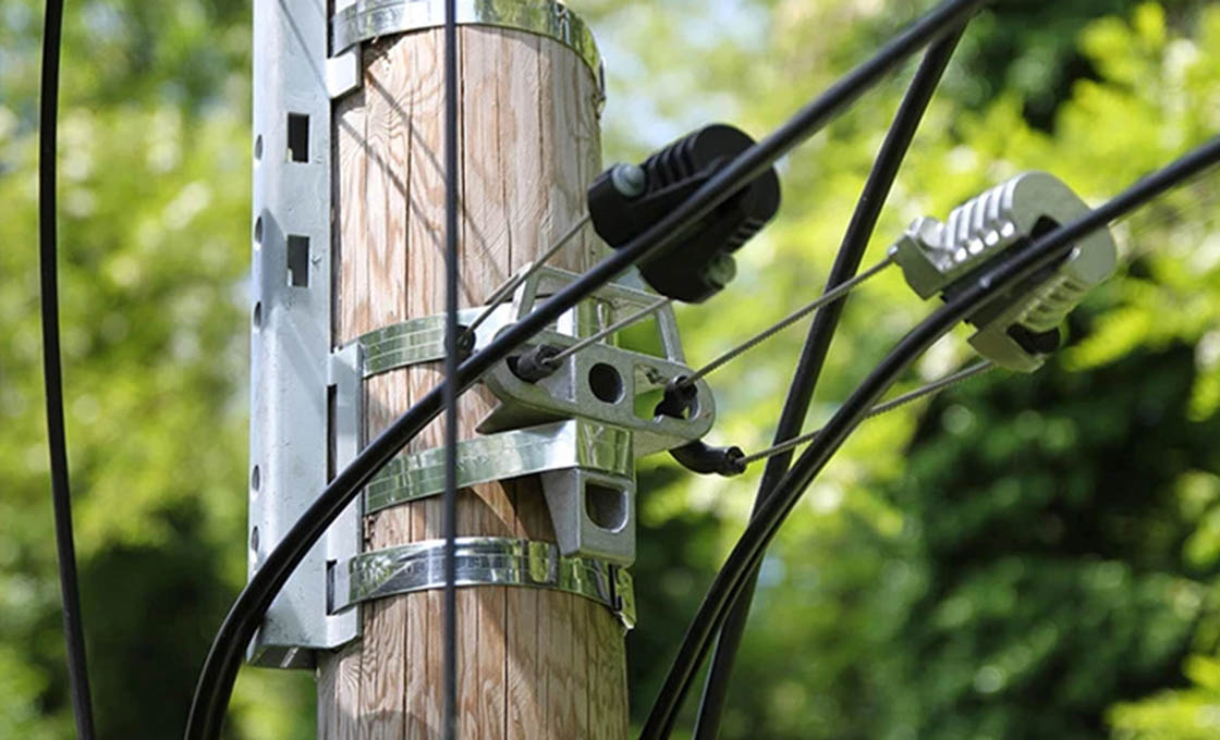
Bolt Mounting: The Fixed Joint on Wood Poles
Wood poles are drilled as a matter of routine, so the bolt is the default there. The datasheet asks for a 14 or 16 mm bolt through the bracket’s center hole. Sixteen millimeters matches the 5/8-inch machine bolt that field practice treats as the standard size class for wood-pole attachments.
IEEE C135.1 covers zinc-coated bolts and nuts for overhead line construction, the fastener family behind the 5/8-inch machine bolts that carry pole line hardware on wood poles.
Length matters as much as diameter. The datasheet sets the minimum at the pole diameter plus 50 mm, which leaves full thread for the nut wherever the bracket lands on the taper. Washers under the head and the nut spread the load, and the nut, not feel, sets the tightness.
Pre-drilled concrete poles take the same route. Where the pole maker cast fixing provisions into the concrete, the bracket bolts straight to them with no banding tool in sight. Check height and rotation against the line design first, because a cast hole fixes both.
Long bolts bring one more field detail. Under IEEE C135.1, machine bolts in the longer sizes carry semi-cone points, so the bolt drives through drilled wood without the thread chewing the hole. Tap the cone through, seat the bracket, and run the nut up.
Choosing Between Bands and Bolts Job by Job
Neither route wins in the abstract. The pole in front of the crew picks the method, and a short decision table settles it faster than debate.
| Pole situation | Mount with | Why |
|---|---|---|
| Sound wood pole | Bolt | Drilling is routine, and the joint is rigid and fixed |
| Concrete pole without cast holes | Bands | No drilling, so spun concrete stays untouched |
| Concrete pole with cast provisions | Bolt | Uses the fixing the pole was designed with |
| Steel or tubular pole | Bands | The protective coating never gets breached |
| Temporary or reversible attachment | Bands | Removal leaves the pole exactly as found |
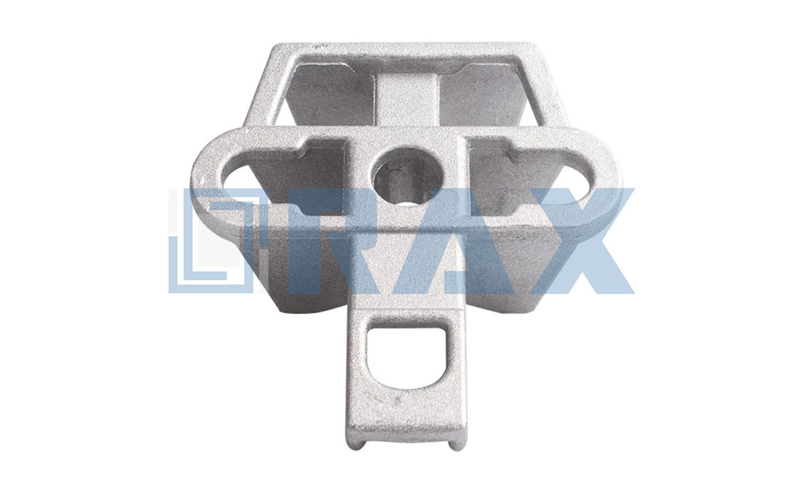
Load class rarely flips the choice. The anchoring clamp pole bracket carries a working load of 5 kN or better, which covers typical clamp duties on distribution and fiber routes. When a design pushes past that, the answer is a larger fitting or a crossarm, not more tension on a strap.
One more input belongs in the decision: what the pole will carry next. A route that grows a second or third dead end later rewards the bolted joint, because the bracket is already fixed at a known position. A short-term attachment on a concrete pole still argues for bands, whatever the five-year plan says.
Position and Load Direction at the Pole
When the bracket goes up, its height comes from the line design, not from eye judgment. The body must sit plumb on the pole face, because a tilted bracket pulls the bail sideways and turns pure tension into a twist. Both load the joint in directions it was not meant to take.
Load direction then decides the aperture. The five holes exist so the bail, a roller, or a stay-off can sit in the position that keeps the pull straight through the joint. Dead-ending one, two, or three parallel lines from one body is a listed application. Each extra clamp adds load, and the sum still exits through one bolt or two bands.
Watch the bail after the clamp hangs. It should sit fully home and swing free enough to follow the span. A bail that binds works the joint loose a little at a time. The anchoring clamp range page covers the clamp side of that pairing.
The same apertures serve the work before energization. The application list includes running out rollers for stringing, jointing points, and derivation points, all fixed to the same body. A bracket that carries the stringing roller and then the finished dead end saves a second trip up the pole.
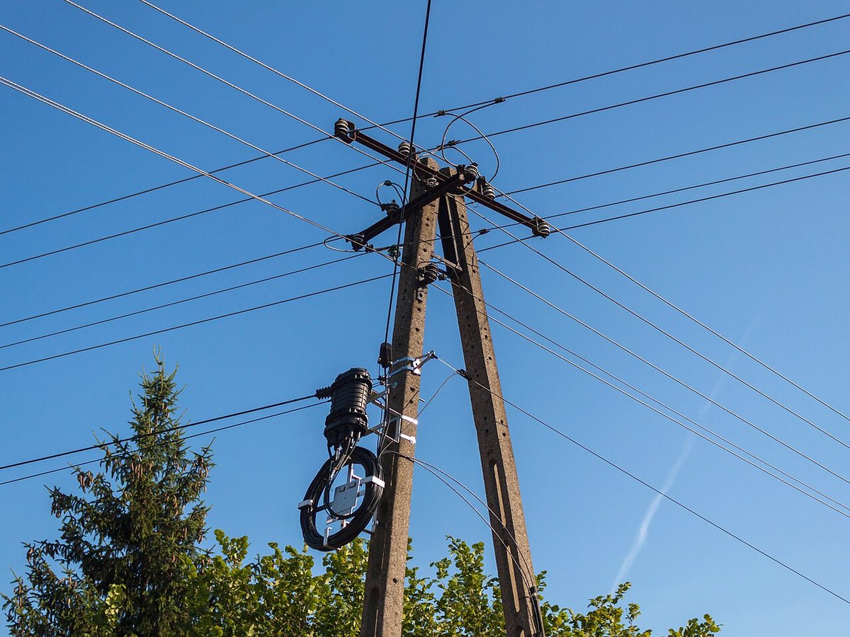
What a Finished Mount Must Show Before You Leave
In our experience, most anchoring clamp pole bracket complaints in service are joint complaints that a thirty-second check would have caught. Before the bucket comes down, look for four things.
- Bands tight and locked, with no daylight under the strap and buckle tails cut flush.
- Bolt nuts fully engaged, washers seated, and zero movement when the bracket is pushed by hand.
- Body plumb on the pole face, with the bail fully home in its aperture and free to swing.
- Surfaces undamaged, with coating intact on steel poles and no fresh cracking around bolt holes on concrete.
Keep a photo of the finished joint with the span record. Paper notes fade, but a timestamped image shows any later inspector exactly what was fitted, on which pole, on which day.
Match the Mount to the Pole in Front of You
An anchoring clamp pole bracket earns its keep at the joint, and the joint rewards matching the method to the pole. Bands on concrete and steel. A sized bolt on wood or pre-drilled concrete. Two 20 x 0.7 mm straps or one bolt of pole diameter plus 50 mm, finished with a hand check before the crew leaves the pole.
RaxPower builds the bracket, its fixings, and the anchoring clamps it carries on one ISO 9001 certified line, so the ratings across the set stay comparable. Pick the bracket for the clamp’s load path, pick the mount for the pole, and the dead end will outlast the span it holds.
Frequently Asked Questions About Mounting a Pole Bracket
Can one bracket design serve wood, concrete, and steel poles?
Yes, when the datasheet gives both mountings. The bracket in this guide mounts with two bands or one bolt, so the pole material picks the route rather than the hardware.
What size bolt mounts a pole bracket on wood?
Follow the datasheet first: 14 or 16 mm here. Sixteen millimeters equals the 5/8-inch machine bolt class common on wood poles, with bolt length at least the pole diameter plus 50 mm.
Is banding strong enough for an anchoring clamp pole bracket?
For its rated duty, yes. The bracket body carries a working load of 5 kN or better, and the datasheet applies that rating to the bracket itself. Match the bracket and clamp ratings to the span design before choosing the mounting.
Can I drill a concrete pole to mount a bracket?
Treat drilling as a last resort and prefer cast provisions or bands. If drilling is approved, guidance for prestressed concrete poles calls for a bit about 3 mm oversize, drilled from both faces to prevent blowout.
What does a correct bracket mount look like?
A plumb body, tight bands with locked buckles or fully engaged bolt nuts, no movement under hand pressure, and a bail that sits home and swings free. Anything else gets corrected before the span takes load.