
Picture the last dead-end structure before the substation. The ADSS cable arrives under full stringing tension, and every newton of that load transfers through one fitting set. If that set was chosen for a different cable diameter, a different span class, or a lower breaking load, the junction becomes the weakest link on an otherwise sound route. Selection errors stay invisible during commissioning, then surface as slipped jackets, climbing attenuation, or cable on the ground after a storm.
Since 2003, RaxPower has manufactured pole line and overhead line hardware for utilities, line contractors, and distributors. Its 170+ employees work under an ISO 9001 quality system. The sections below condense what a correct tension-side selection must verify. That covers the fitting set itself, the cable OD and RTS behind it, the span class above it, and the checks that happen before dispatch.
What a Tension Point Asks of Fittings
At a dead-end, a corner pole, or a terminal structure, the hardware carries the full mechanical tension of the span. Suspension assemblies play a different role. Preformed suspension fittings are rated to hold roughly 10 to 20 percent of the cable RTS, cushioning the cable while it passes a tangent support. Asking support hardware to anchor is the most basic selection error in a tension schedule.
This role test comes before any comparison of brands or prices. Tension positions appear more often than a route map suggests: every terminal pole, every large-angle corner, and every tensioning tower along the line needs one. A route with a dozen direction changes carries a dozen places where the wrong fitting class could hide. The support side has its own selection logic, covered in detail in this suspension clamp guide. The rest of this article stays on the tension side, where the stakes are highest because the fitting holds the entire span.
Inside a Preformed Tension Clamp Set
The standard set is a kit of helically formed components. An inner preformed rod wraps the cable first, an outer preformed rod layers over it, and a pulling ring closes the assembly for attachment to the structure link. Kit form matters: a set supplied without its thimble or link hardware cannot be rated as a unit.
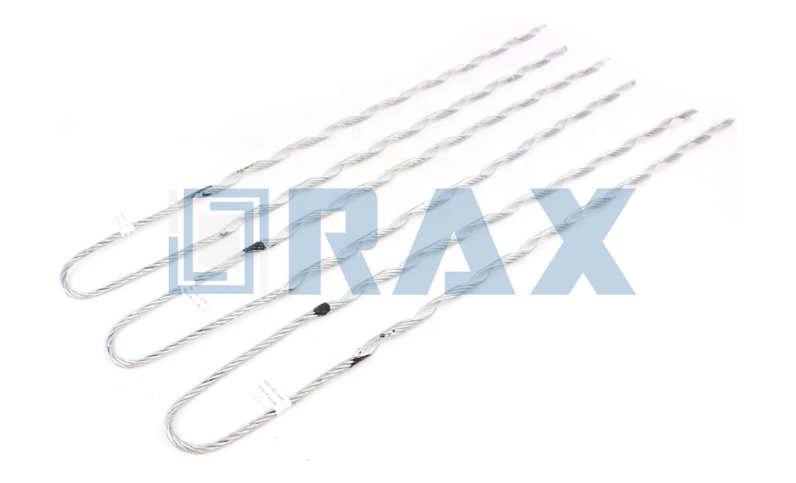
For ADSS, the rods are made of aluminum-clad steel or aluminum alloy. The helical lay spreads the holding force along a long contact length instead of concentrating it at two bolt points. Because no single point carries a disproportionate share of the load, the set also avoids localized stress on the jacket and adds a measure of vibration damping for free. That distributed grip is the core engineering argument for preformed fittings on any all-dielectric, self-supporting route.
Match Cable Diameter Before Anything Else
Every ADSS tension clamp is built for a diameter window, typically only 2 to 4 mm wide. A cable whose nominal OD sits at the edge of that window is technically in range. In practice it is at risk, because jacket tolerance can push the real diameter outside the grip zone. Published diameters are nominal, and as-built OD can differ by about 0.5 mm. Double-jacket cables run 2 to 4 mm larger than single-jacket designs at the same fiber count, so fiber count is never a proxy for size.
Measure the delivered drum with calipers at several points, then confirm the figure against the cable manufacturer’s test report. Sizing references such as this ADSS clamp sizing guide publish per-window tables, and they vary between brands. A 13 to 16 mm clamp from one maker will not automatically match another brand’s number, and the main ADSS fitting families differ in how tightly each window is defined.
Manufacturers treat diameter as its own specification axis. PLP’s dead-end catalog splits ADSS sizes into windows about 1 mm wide, each marked with a color code, and AFL model numbers encode the OD range the same way. Two cables that look identical on a reel can therefore demand different ADSS tension clamp fittings, which is why the drum label never settles the question.
Why Grip Strength Is Rated Against RTS
RTS, the rated tensile strength, describes the longitudinal force a cable survives before its strength members fail. Industry practice rates a correct tension set to hold at least 95 percent of that value without slipping or damaging the cable. Grip below that threshold does not announce itself at handover. It shows up as creep under cyclic wind and thermal loading, wearing the jacket a fraction of a millimetre at a time.
Contact length is part of the same rating logic, and some suppliers publish minima tied to span. Common guidance calls for rod contact of at least four times cable OD on spans up to 500 m. For longer spans the guidance rises to six times OD. A short rod bed concentrates load at its ends, so contact length is not optional padding.
Temperature adds a slower threat. Aluminum moves noticeably more than steel with temperature, while polyethylene jackets cold-flow under sustained pressure. A set that fit on installation day can therefore relax over years of service. Concentrated pressure can also raise fiber attenuation as micro-bend stress builds in the core.
Span and Terrain Decide the Set Class
Suppliers grade ADSS dead-end sets by span and tension class rather than offering one universal design. Single-layer tension sets are positioned for short spans of roughly 50 to 200 m at corner, tensioning, and terminal structures. Dedicated short-span, low-tension products such as PLP’s FIBERLIGN Lite dead-end confirm how finely the market splits these classes, and heavier multi-rod sets take over as spans and loads grow.
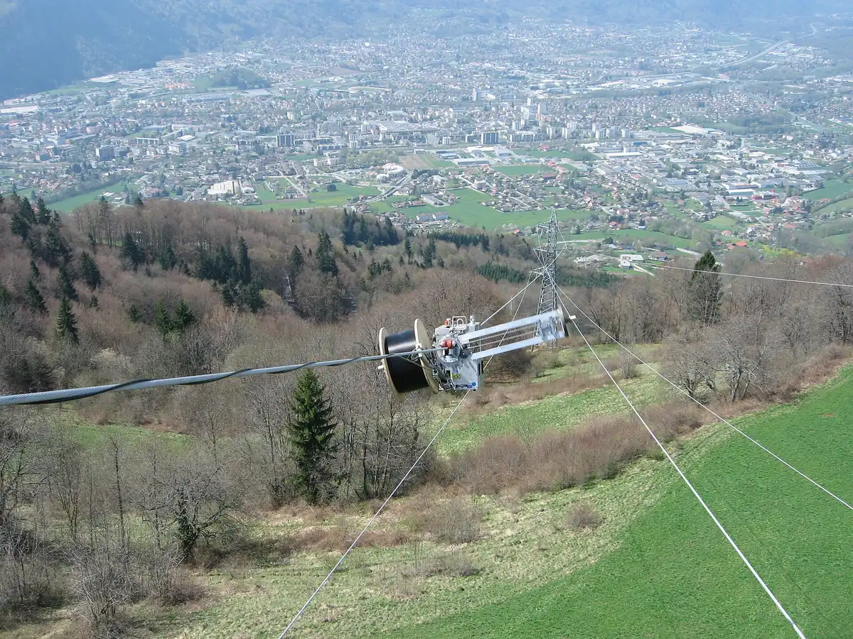
Terrain multiplies the demands. Crossing a river or a valley lengthens the span, raises design tension, and narrows the list of suitable ADSS tension clamp fittings. Angle is the second terrain variable. A dead-end thimble can carry up to four formed-wire sets and hold tension angles up to 90 degrees. That is why large-angle corners are treated as tension positions rather than tangent ones.
Sharing a structure with a high-voltage circuit adds another filter. Lines at 220 kV and above call for corona rings at fitting ends to limit jacket corrosion. Where an anchoring position needs a walk-through of the hardware itself, this anchoring clamp walkthrough covers the fitting in place.
What Goes Wrong When the Fit Is Wrong
An oversized set cannot constrict far enough, so the cable slides under load the way you can pull a belt through a buckle one size too large. Each load cycle adds micro-movement, polishing a shiny band into the jacket and eroding it a little further every time. An undersized set fails in the opposite direction: the rods bottom out and crush the jacket, creating micro-bend stress that raises attenuation over time.
Slippage is self-accelerating, because the polished zone has less friction than intact jacket. One detailed failure analysis ranks clamp slippage as the most common cause of unplanned ADSS outages after storm damage. By the time a crew notices the problem, the wrong fit has usually been on the pole since installation day.
In our experience, a shiny band just outside the rod zone points to a sizing error rather than an installation error. So do rods that turn by hand. Both signs trace back to the ordering stage, not to the crew that hung the set.

Preformed Rod Sets or Bolted Tension Clamps
Both families exist, and choosing between them is itself a selection decision. Preformed rod sets distribute grip along a long helical contact length, install without torque tools, and are the default dead-end answer for ADSS. Bolted tension clamps hold through clamped jaws, which concentrates pressure where the bolts meet the shell. On a soft polyethylene jacket, that point pressure is exactly what protective rod layers exist to prevent.
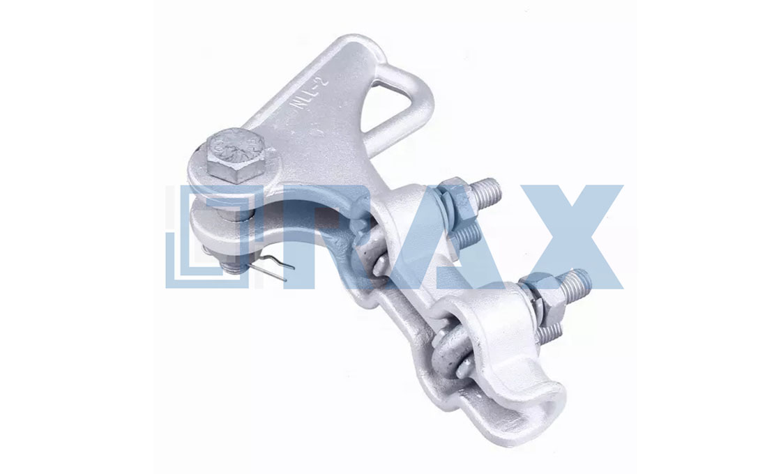
Bolted designs remain common on bare conductors, where their stiffness earns its keep. When a project schedule lists a bolted dead-end for ADSS, the specification should state how the jacket is protected at the jaws. If that explanation is missing, the gap is a selection problem, not an installation detail.
Compatibility Checks to Run Before Buying
A short checklist catches almost every mismatch before it ships. Run it per structure, not per project, because span class and angle can change between poles on the same route.
- Confirm as-built cable OD with calipers and the test report, and check it sits near the center of the clamp window.
- Match the set rating to the cable RTS and the design span tension, expecting a grip of at least 95 percent.
- Classify each structure as dead-end, corner, or terminal, since the line angle changes the required hardware kit.
- Verify span class against the supplier’s own table instead of assuming one clamp serves all spans.
- Check kit completeness: inner and outer rods, thimble or pulling ring, and the linking hardware for the structure.
- Note jacket type and circuit sharing, because double-jacket and AT cables change both diameter and accessory needs.
Sizing tables are brand-specific, so avoid pairing a cable from one supplier with clamps from another without written confirmation. Sourcing the cable and the ADSS tension clamp fittings together turns the interface into a tested system rather than a guess. The ADSS and OPGW fitting range gathers the tension-side sets and accessories in one catalog for exactly that reason.
One last habit closes the loop between paper and pole. Record the set number against the cable drum number for every structure. Attach the thimble to hardware rated for the same load path rather than whatever is on the truck. If any line of the schedule cannot be answered from a data sheet, treat that silence as a stop sign for the order.
Field Evidence of a Mismatched Tension Clamp
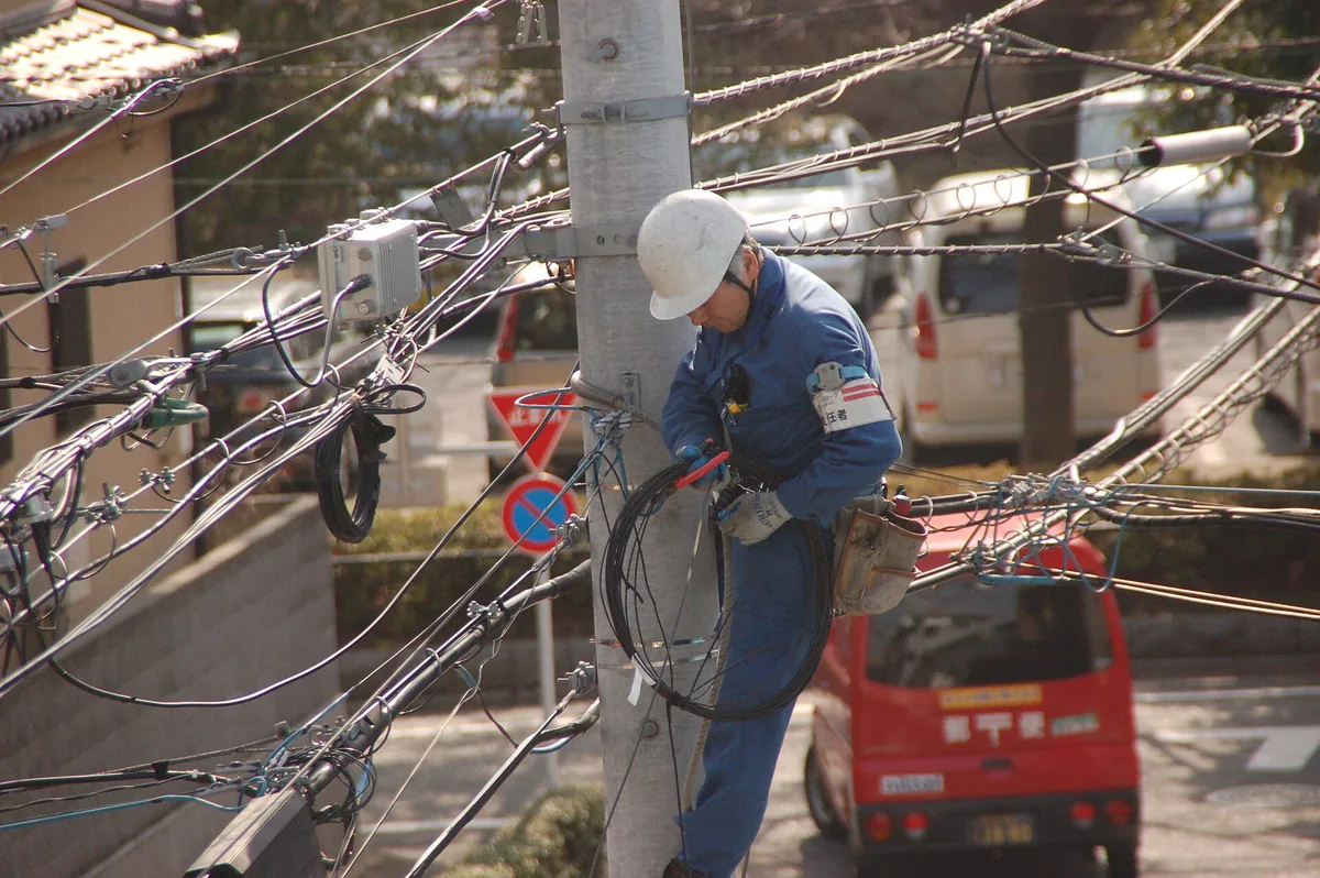
Field checks find what catalogs cannot. On a routine patrol, four observations separate a healthy tension point from a suspect one.
- Rods that rotate by hand signal an undersized fit, because a correct set should be immovable on the cable.
- A polished band 5 to 15 mm wide just outside the rod coverage marks micro-slipping in progress.
- A visible neck-down of the jacket at the rod exit indicates the cable has been moving under load.
- Attenuation that climbs after wind events suggests grip loss redistributing stress into the cable.
Any one of these signs justifies re-checking the original cable data against the installed ADSS tension clamp fittings. Log the set number alongside the cable drum number while the route is still on paper, and the patrol crew will know exactly what to compare. RaxPower manufactures its pole line and overhead line hardware to the same discipline described here. Matching sets to cable data rather than catalog habit keeps the cheapest repair in place: the mismatch that never ships.
Key numbers for ADSS tension clamp fitting selection
- Tension (dead-end) sets are rated to hold at least 95 percent of cable RTS; suspension fittings hold only about 10 to 20 percent.
- Clamp diameter windows run roughly 2 to 4 mm wide, with as-built cable OD varying about 0.5 mm from nominal.
- Double-jacket ADSS cables measure about 2 to 4 mm larger than single-jacket designs at the same fiber count.
- Single-layer tension sets suit spans of roughly 50 to 200 m; longer spans need higher span-class sets.
- Published grip-length minima: about 4 times cable OD for spans up to 500 m, and about 6 times OD beyond that.
- Slip evidence to log: hand-rotatable rods and a polished band 5 to 15 mm wide outside the rod zone.
Frequently Asked Questions
What fittings make up a complete ADSS tension clamp installation?
A standard set contains an inner preformed rod, an outer preformed rod, and a pulling ring, plus a thimble and link hardware where the structure needs them.
How strong must an ADSS tension clamp grip be?
Industry practice rates tension sets to hold at least 95 percent of the cable RTS without slipping or damaging the jacket.
Can a suspension clamp anchor an ADSS cable at a dead-end?
No. Suspension fittings hold roughly 10 to 20 percent of RTS, so they support the cable at tangent poles but cannot carry span tension.
Do short spans and long spans need different tension sets?
Yes. Suppliers grade sets by span class, with single-layer designs for roughly 50 to 200 m and heavier multi-rod sets for longer, higher-tension spans.
How do I confirm the clamp size matches my cable?
Measure the cable OD with calipers, confirm it against the test report, and check it sits near the center of the clamp’s diameter window.