
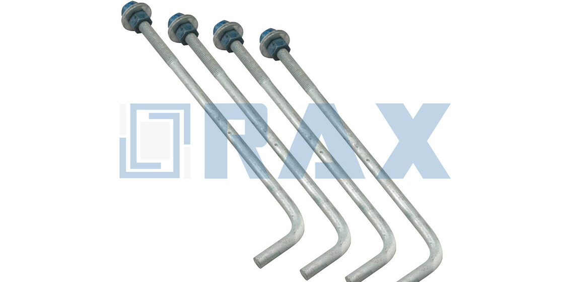
Confusing a bolt circle measurement with a bolt square measurement is the primary cause of base plate incompatibility in utility installations. A bolt circle defines the diameter of an imaginary ring passing through the bolt centers, while a bolt square measures the distance between the parallel sides of the square they form. If you treat a square pattern as a circle pattern, or vice versa, the light pole bolt pattern will not align with the foundation anchors, regardless of how accurately you poured the concrete.
We analyze how radial load distribution in circular configurations compares to the moment resistance offered by square layouts under wind load. You will learn to select the correct geometry based on specific engineering standards and site constraints to ensure structural integrity.
How Circle vs. Square Patterns Support Load
Circular patterns provide uniform radial distribution ideal for round poles and unpredictable wind directions, whereas square patterns offer high directional efficiency but introduce stress concentration risks if the load vector shifts.
Radial Load Distribution in Circular Patterns
In the context of round tapered light poles, the circular anchor bolt pattern—often referred to as a bolt circle—is engineered to maximize symmetry. The primary advantage of this geometry is that every anchor bolt maintains an identical distance from the pole’s central neutral axis. When vertical loads or moments are applied, this equidistant lever arm ensures that tension and shear stresses are distributed evenly across all fasteners simultaneously. For utility projects facing unpredictable environmental vectors, this uniformity prevents individual bolts from becoming overloaded while others remain under-utilized. Our experience in export markets shows that circular patterns significantly reduce the risk of base plate fatigue over the pole’s lifespan because the stress is shared equally rather than isolated at specific points.
Moment Resistance Comparison: Circle vs Square
The debate between circle and square patterns often centers on moment resistance—the structural ability to resist rotation or bending. A square pattern, defined by its four corners, effectively places two bolts on the neutral axis and two bolts at the maximum lever arm distance when the load aligns with the diagonal. This can theoretically offer slightly higher moment capacity along that specific diagonal axis compared to a circle of similar overall size. However, this comes with a trade-off: if the wind load or force vector shifts to align with the flat side of the square, the lever arm for the resisting bolts decreases, reducing moment capacity.
Conversely, a circular pattern maintains a constant lever arm regardless of the direction of the applied force. In our manufacturing analysis, the square pattern is efficient for structures with rectangular base plates where the load path is known and constant. But for round poles where wind direction is dynamic, the circular pattern provides more reliable and consistent moment resistance across 360 degrees. We find that relying on a square pattern for round poles often requires over-engineering the bolt grade to compensate for the geometric efficiency loss at off-peak angles.
Wind Load Alignment with Bolt Geometry
Wind load alignment is the critical variable that dictates which specific anchor bolts will experience peak tension. Under high wind conditions, the pole acts as a cantilever beam, inducing uplift on the upwind side and compression on the downwind side. In a circular layout, the “upwind” bolts are always positioned at the maximum distance from the neutral axis, providing optimal resistance to overturning moments no matter where the wind comes from. This geometry ensures that the concrete embedment is consistently engaged.
Wind load alignment dictates which specific anchor bolts experience peak tension under high wind conditions. With a square pattern, if the wind load aligns with the face of the base plate, tension is distributed across two bolts to provide higher capacity. However, corner loading concentrates tension on a single bolt, effectively reducing the anchorage efficiency in that orientation. Circular patterns provide optimal resistance regardless of wind direction because they maintain a consistent maximum distance from the neutral axis. Consequently, the precision of the layout is paramount; even a minor deviation in the template during concrete pouring can misalign the geometry, compromising the calculated wind load resistance.
When designing for square patterns on high-load projects, we frequently recommend increasing the bolt circle diameter (or square size) rather than just upsizing the bolt grade. Increasing the geometric spread maximizes the lever arm, which yields a higher return on moment resistance than simply using stronger steel in a tighter pattern.
| Feature | Specification | Advantage |
|---|---|---|
| Anchor Bolt Pattern | 3, 4, or 8 bolt configurations | Tailored to specific light pole base designs for optimal stability |
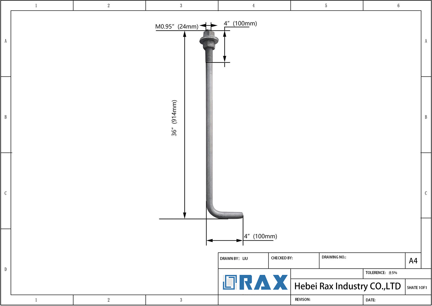
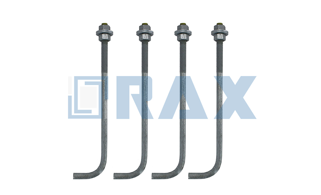
| Bolt Configuration Types | Straight rods (double-ended), L-shaped bent bolts, fully threaded rods | Customized pull-out resistance based on structural load requirements |
| Template Compatibility | Steel templates matching bolt circle patterns | Ensures precise alignment and eliminates installation delays |
| Fastener Assembly | 6 nuts and washers per rod (straight/fully threaded); 2 nuts and washers per rod (bent/headed) | Secure sandwiching of base plate and embedded templates in concrete foundation |
Meeting Engineering Standards for Each Layout
Selecting the correct anchor bolt layout—either a circular pattern or a square pattern—is a fundamental engineering decision that dictates structural integrity and installation feasibility in pole line hardware projects. The primary pain point engineers face is ensuring that the chosen geometry aligns with load distribution requirements while remaining compatible with site-specific foundation constraints.
Circular patterns excel at radial load distribution and wind alignment, whereas square patterns offer simplified template fabrication and precise moment resistance in specific axes. Selection must depend on jurisdictional standards (AASHTO/IBC) and actual field tolerance conditions rather than generic assumptions.
Comparative Analysis of Layout Geometries
Engineers often confuse the measurement techniques required for these two configurations, leading to specification errors during the procurement phase. Understanding the technical distinction between Bolt Circle Diameter (BCD) and Bolt Square is essential for accurate ordering and foundation preparation.
- Bolt Circle: Defined by the diameter of the circle passing through the center of each bolt hole. This measurement is critical when analyzing moments applied from multiple directions, such as swirling wind loads. It requires precise template plate positioning before concrete pouring.
- Bolt Square: Measured as the straight-line distance between the centers of opposite bolts (forming a square). This layout simplifies the calculation of rectangular base plates but may require careful conversion to Bolt Circle if design calculations assume radial symmetry.
Regulatory Alignment and Jurisdictional Requirements
Different regions and governing bodies impose distinct preferences based on historical precedent and local soil conditions. For instance, AASHTO standards often dictate specific geometries for highway infrastructure where lateral wind forces are unpredictable, favoring the uniform stress distribution of a circular layout. Conversely, IBC-compliant commercial sites might utilize square layouts for their ease of integration with standard rebar grids found in concrete footings.
Comparing Costs and Material Efficiency
When evaluating total project expenditure, square 4-bolt patterns typically reduce fabrication and layout labor due to simpler geometry, whereas circular patterns may incur higher initial tooling costs but can optimize material distribution in specific base plate designs.
Measurement Complexity and Labor Costs
The most immediate cost difference between bolt square and bolt circle configurations lies in the verification and layout processes. For square patterns, field crews can determine accuracy by measuring the straight-line space between adjacent bolts. This simplicity allows for rapid verification using standard tape measures, reducing crew time on site.
Conversely, circular patterns require precise measurement of the Bolt Circle Diameter (BCD). This often involves measuring across diagonally opposed bolts or using specialized bolt circle calculators to convert chord lengths. If anchor rods are set even slightly out of tolerance, correcting circular patterns during concrete pouring is significantly more labor-intensive than adjusting square layouts. Selecting a configuration that aligns with standard field measurement tools can decrease installation hours by up to 15% on large-scale projects.
Steel Utilization and Base Plate Fabrication
Material efficiency is heavily influenced by the geometry of the base plate. Square patterns are inherently compatible with square base plates, which are typically cut from standard steel sheets with minimal waste (“nesting efficiency”). This reduces raw material scrap rates during the manufacturing phase.
Circular patterns, however, usually require round base plates. When fabricating round plates from square sheets, manufacturers generate significant corner waste (scrap) unless these offcuts can be utilized for smaller components. While circular designs can sometimes reduce overall plate weight by distributing load closer to the center, the fabrication cost per kilogram of processed steel is often higher due to increased cutting energy and waste handling. Contractors must balance the potential for lighter individual components against the higher raw material waste factor associated with circular geometries.
Precision Tolerance and Lifecycle ROI
Dimensional accuracy of hardware directly influences erection risk and field modification costs. High-precision manufacturing, such as automated machining for steel cross arms, ensures tight tolerances that minimize misalignment during pole erection. While generic bolts with standard industry specifications may have a lower upfront unit price, they increase the risk of costly field modifications, such as reaming holes or grinding base plates.
Furthermore, material efficiency extends to service life. Utilizing hot-dip galvanizing technology with a mean coating thickness exceeding 85 microns—significantly above the industry minimum—ensures corrosion resistance in harsh environments. This specification reduces the long-term ownership cost by deferring maintenance cycles and preventing premature foundation failures, offering a higher return on investment despite a marginal increase in initial material costs.
- Layout Efficiency: Square patterns reduce verification time to simple side-to-side measurements, whereas circular patterns require complex diagonal calculations.
- Material Waste: Square base plates optimize steel sheet usage with minimal scrap, while round plates generate higher material waste during fabrication.
- Fitment Tolerances: Strict dimensional control (e.g., 1mm tolerance) prevents expensive field rework, ensuring the base plate fits the anchor array without modification.
- Corrosion Protection: Coating thicknesses exceeding 85 microns (ISO 1461) lower lifecycle costs by extending the service interval in corrosive soils or atmospheres.

Which Pattern Fits Your Site Conditions?
Selecting the correct bolt pattern is not merely a matter of pole specification; it is dictated by the interplay between soil mechanics, seismic activity, and the physical constraints of the installation site.
Soil Stability and Foundation Geometry
The bearing capacity of the sub-grade soil is the primary determinant of the foundation type, which in turn dictates the optimal anchor bolt pattern. In sites with high-load bearing capacity, such as dense rock or compacted gravel, smaller diameter footprints using square patterns are often sufficient. However, in loose or sandy soils where vertical uplift is a significant risk, engineers typically specify circular patterns with larger diameters.
Circular patterns allow for a wider distribution of the tension load generated by the pole’s moment arm. This configuration is particularly effective in cohesive soils where the concrete pier must rely on skin friction and the weight of the soil cone to resist pull-out forces. The symmetry of a bolt circle ensures that regardless of the wind direction, the tension is evenly transferred to the surrounding soil mass.
Seismic Zones and Dynamic Load Paths
In regions characterized by high seismic activity, the selection criteria shift from static load resistance to dynamic energy dissipation. Seismic events induce complex, multi-directional forces on utility infrastructure. While square patterns provide Strong resistance to unidirectional bending (typical of prevailing winds), circular patterns generally offer superior performance under torsional stress.
High-seismic zones frequently favor circular configurations with increased anchor quantities. This layout minimizes stress concentrations at the corners of a base plate—a common failure point in square patterns during lateral shaking. additionally, the use of fully threaded rods or specific bolt styles in these zones allows for the “sandwiching” of the base plate with heavier nut and washer assemblies, ensuring the pole base remains secured even during significant ground acceleration.
Pole Height and Arm Configuration
The physical dimensions of the pole and its associated hardware act as a lever, amplifying the forces transferred to the foundation. Standard street lighting poles under 15 meters typically utilize square bolt patterns due to their lower overturning moments and the prevalence of square base plates in standard inventory. Conversely, high-mast lighting poles (30m+) and heavy-duty utility poles equipped with large steel cross arms generate substantial overturning moments.
For these taller installations, circular patterns are the industry standard. The larger bolt circle diameter accommodates the massive base plates required to distribute these high loads. When a site requires the mounting of heavy equipment or multiple cross arms, the circular arrangement provides the necessary geometric flexibility to align with complex structural geometries without compromising the edge distance of the concrete foundation.
Site upgrade failures often stem from geometric confusion between bolt circles and bolt squares during retrofit verification. Always verify the geometric definition of the pattern—center-to-center diameter versus side-to-side width—before fabrication to ensure proper base plate alignment and installation.
Site Access and Urban Constraints
In dense urban environments or constrained easements, the physical footprint of the foundation excavation is a limiting factor. While circular patterns are structurally efficient for high loads, they may require larger diameter excavations than square patterns for similar load capacities in stable soil. If the site is adjacent to underground utilities or other infrastructure, a square pattern might be specified to minimize the horizontal footprint of the pier.
Additionally, accessibility for installation equipment plays a role. Templates for circular patterns can be more cumbersome to maneuver in tight trenches compared to square templates. Contractors must weigh the structural benefits of a circular layout against the logistical feasibility of placing the template and pouring concrete in a restricted access area.
| Bolt Style Options include straight rods, L-shaped bent bolts, fully threaded, or headed types optimized for structural requirements. | ||
| Template Integration utilizes steel templates matching bolt circle patterns to ensure precise pole alignment during installation, eliminating delays. | ||
| Hardware Assembly specifies nut and washer counts per rod type to secure sandwiching within the concrete foundation. | 6 nuts and washers per rod for straight/fully threaded; 2 nuts and washers for bent/headed types | Secures base plate and embedded templates. |
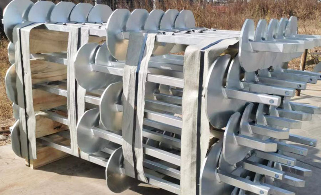
| Manufacturing Precision | Manufacturing Precision leverages automated hot-forging production to deliver superior strength over traditional casting methods. | Superior strength and precision over traditional casting methods |
Verify Your Choice and Avoid Risks
Mismatched anchor bolt patterns remain a primary cause of installation delays requiring precise geometric fitment. Verifying whether your specification calls for a Bolt Circle or Square pattern before ordering is essential to prevent template misalignment with the foundation’s rebar cage, which would otherwise necessitate costly core drilling or epoxy repairs that risk structural integrity.
Foundation Tolerance Impact on Pattern Selection
The concrete foundation pour is the single most critical phase for pattern selection. If your template is not aligned with the poured foundation’s rebar cage during casting, correcting it afterward requires expensive core drilling or epoxy repair, risking structural integrity. A deviation greater than 3mm in the bolt square dimension will prevent the steel base plate from seating flush, causing eccentric loading that compromises wind resistance calculations.
Template specification during anchor bolt ordering ensures foundation alignment matches manufacturing precision. Steel templates are required to verify fitment against foundation boreholes, as Rax Power automated production reserves strict 1mm dimensional tolerances for steel cross arms per the Product Bible. We recommend verifying the actual borehole alignment against the template design before the concrete cures to avoid the “bolt circle mismatch” error.
Verification Steps for Anchor Layout Compliance
To ensure compliance before ordering final hardware, perform these verification steps on-site:
- Diagonal Check: Measure the distance between two diagonal anchor bolts (corner to corner) to determine the Bolt Circle. This value should match the circular diameter specified in the engineering drawing.
- Adjacent Check: Measure the center-to-center distance between two adjacent bolts to establish the Bolt Square. This linear measurement confirms the rectangular footprint of the pattern.
- Tolerance Audit: Cross-reference both measurements against the ASTM standards applicable to your region. Any variance exceeding 1-2mm indicates a potential fitment issue with standard cross-arms or base plates.
📋 Expert Action Plan
- Step 1: Conduct a site survey to measure existing foundation anchors or verify new formwork alignment.
- Step 2: Specify both Bolt Circle and Bolt Square dimensions in your purchase order template section.
- Step 3: Request Rax Power to manufacture custom molds if the site conditions deviate from standard 4-bolt patterns to guarantee hot-forging accuracy.
Over-Engineering Risks in Bolt Configuration Choice
A common mistake in B2B procurement is over-engineering the bolt configuration based on theoretical maximum loads rather than practical field constraints. Selecting an 8-anchor bolt pattern where a 4-bolt square suffices increases material costs significantly without improving safety margins for typical light pole applications.
Furthermore, attempting to force a non-standard bolt square into a pre-designed steel cross arm often leads to failed welds or unstable connections. In our experience, strictly adhering to the load distribution geometry provided by the pole manufacturer prevents unnecessary cost escalation while ensuring the galvanizing coating remains intact at critical stress points.
Conclusion
Anchor bolt patterns determine how wind loads transfer to your foundation, and engineering teams must select layouts that match site conditions precisely. Our manufacturing facility produces anchor bolts compliant with ASTM standards for critical infrastructure projects. We recommend square bolt patterns for most light pole installations because they simplify concrete template alignment during construction. This geometry reduces installation errors while maintaining structural integrity under dynamic wind loads. Circular patterns require precise radial measurement that often increases field complications without delivering meaningful performance gains over square configurations in standard utility applications.
Our engineering team supports wholesale partners by reviewing project specifications before finalizing orders. This ensures correct bolt circle or square dimensions align with local foundation tolerances and loading requirements. Share your project dimensions with us for a free technical consultation on anchor bolt configuration. We verify all custom fabrication against established industry guidelines so you avoid costly rework or compliance issues on site.
Frequently Asked Questions
L-bolts or threaded rods: which is better?
L-bolts provide excellent pull-out resistance due to their hooked design anchoring into the concrete, making them ideal for standard tension loads. Fully threaded rods offer flexibility in nut placement and leveling but may require additional anchoring plates for equivalent strength. The choice depends on the specific load requirements of the pole structure.
Is anchor bolt grade important for tenders?
Specifying the correct bolt grade is crucial for ensuring the fastener can handle the designed mechanical loads. Tenders must list the grade to prevent the use of inferior materials that could compromise the pole’s stability. Verification of grade compliance is a standard step in technical tender reviews.
How does galvanization affect bolt longevity?
Hot-dip galvanizing provides a robust barrier against soil corrosion and the alkaline environment of concrete. This protective layer ensures the bolt maintains its tensile strength and structural integrity over the pole’s operational life. Manufacturers like Raxpower utilize ISO 1461 compliant galvanizing to meet these durability requirements.
What load tests should anchor bolts undergo?
Anchor bolts typically undergo proof load testing to verify they can withstand specific tension forces without permanent deformation. Pull-out tests are also conducted to ensure the bond between the bolt and concrete meets safety standards. These tests must comply with international standards like ASTM or IEC to guarantee performance under stress.
How to map BOQ to anchor bolts?
Reviewers must cross-reference the Bill of Quantities against the pole height and base plate drawings to confirm bolt quantity and grade. The anchor bolt configuration, including Pitch Circle Diameter (PCD) and embedding depth, must be explicitly stated to match the physical pole. This verification prevents supply chain errors where incorrect hardware is delivered.