
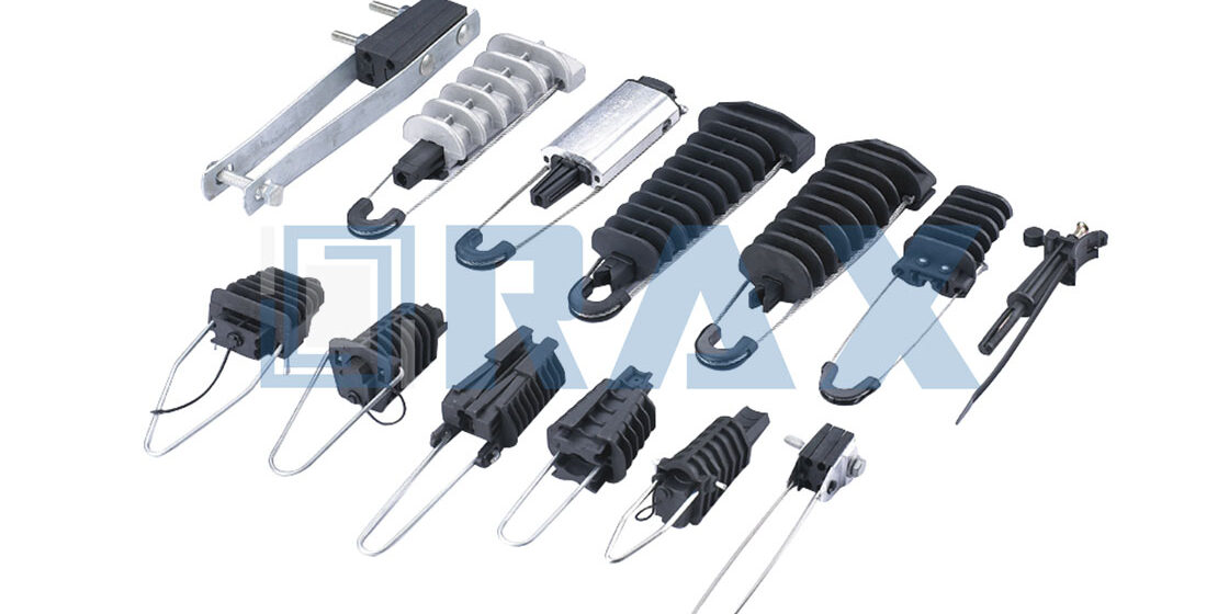
Anchor clamp specs dictate whether a utility network survives a storm or fails under tension — and most procurement directors don’t realize how often the grip strength falls short of field demands. According to GB/T 2314-2008, compression-type anchor clamps must retain at least 95% of the conductor’s calculated breaking force, yet many suppliers quote minimums that barely clear certification thresholds. This gap between spec sheet claims and real-world performance is where grid failures start.
The difference between a compliant clamp and one that slips under ice-load or wind-sway isn’t subtle — it’s measured in millimeters of creep, microns of coating thickness, and seconds before a warranty claim becomes a public outage. We’ve reviewed hundreds of test reports from overseas transmission projects, and the recurring failure point? Bolt-type clamps used on live circuits without proper bonding, creating corrosion hotspots that degrade conductivity within 18 months.
This guide cuts through the vendor fluff and focuses on what actually keeps lines up: material grade selection for salt-air environments, torque specifications that prevent cold deformation, and inspection intervals based on actual degradation rates — not calendar time. You’ll learn why preformed armor rod clamps outperform wedge types in high-vibration zones, and how to verify that your supplier’s 85-micron galvanized coating meets ISO 1461 before the first batch leaves the factory.
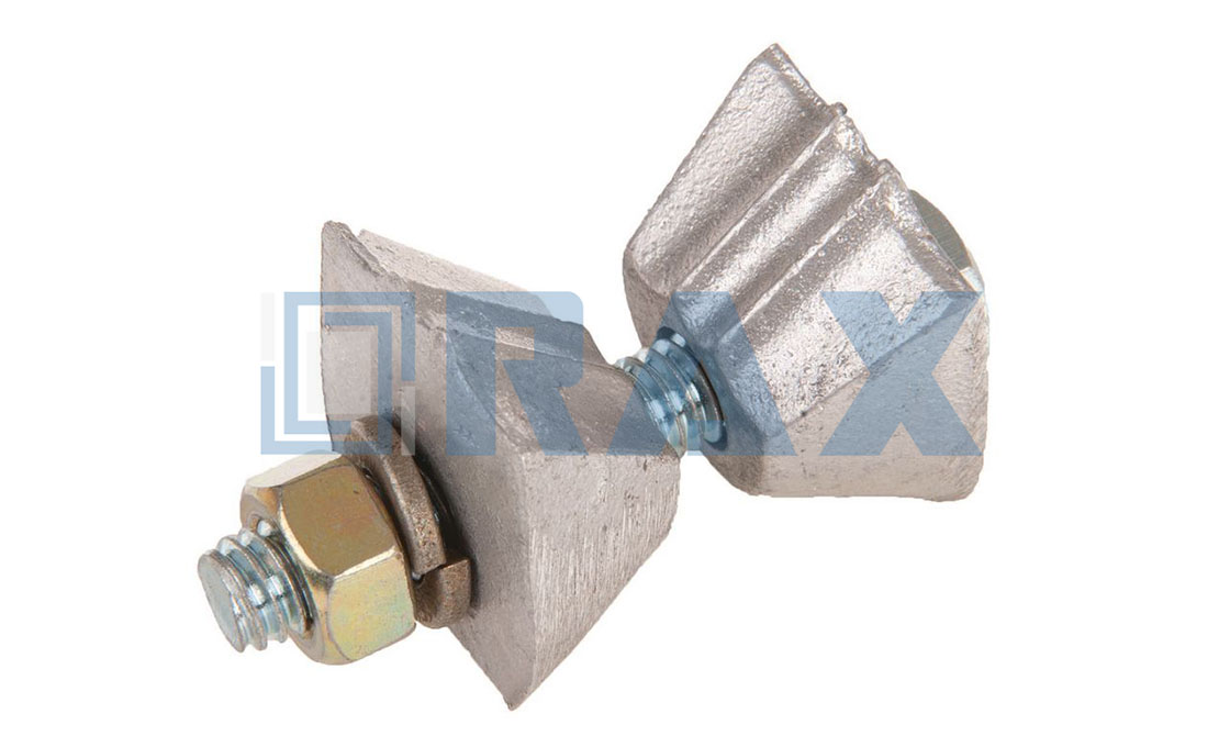
What Are the Different Anchor Clamp Types?
Anchor clamps are specialized mechanical terminations designed to secure cables at line endpoints, maintaining structural integrity against tension and environmental stress.
Structural Design Variations in Anchor Clamps
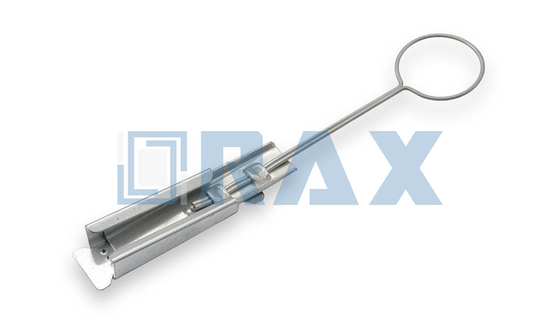
The configuration of an anchor clamp is dictated by its intended role within the overhead line system. The wedge anchor clamp relies on a tapered internal mechanism that generates friction under load without requiring external tightening tools during installation. For parallel cable management, dual-groove housings provide stable alignment across distribution networks where multiple conductors run side-by-side.
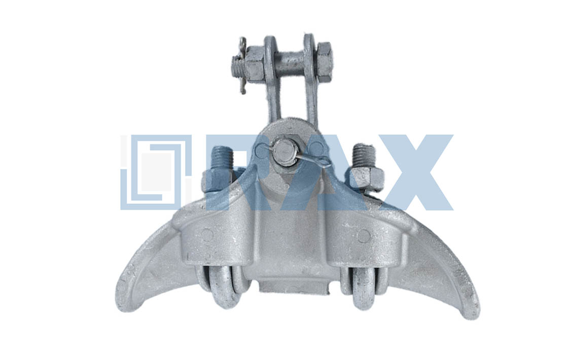
In scenarios demanding vertical flexibility or directional changes, suspension drop clamps utilize flexible housings that allow movement while supporting structural weight at corners or junction points. Conversely, applications requiring precise adjustment and high-tension retention employ bolted fixation systems that offer customizable securing capabilities for heavy-duty setups.
Load Capacity Ratings by Clamp Type
Selecting the correct load rating is critical for preventing slippage or catastrophic failure under maximum wind and ice loads. Mechanical termination anchors represent the high-end of this spectrum, engineered with rigid locking mechanisms capable of managing tension loads up to 15kN at the endpoint.
Beyond absolute strength metrics, we have observed that proper selection depends heavily on matching the grip strength to the specific cable breaking force. Our testing protocols ensure that every unit achieves minimum grip strengths relative to the cable specifications, typically aiming for ratios well above standard industry baselines to account for dynamic loading conditions over decades of service life.
Material Grade Selection for Corrosion Resistance
Environmental exposure dictates the material choices made during manufacturing. While some lighter duty applications may utilize aluminum alloys, heavy-load environments often require galvanized steel constructions to ensure longevity.
To address this, Rax Power implements hot-dip galvanizing technology compliant with ISO 1461 standards. This process ensures a smooth, bright finish with a mean coating thickness exceeding 85 microns. In our experience, this level of zinc protection significantly extends component service life to approximately 20-30 years in corrosive atmospheres, providing reliable durability without frequent maintenance cycles.
| Anchor Clamp Type | Structural Composition | Primary Function | Operational Mechanism | Key Benefit |
|---|---|---|---|---|
| Wedge Anchor Clamp | Plastic (PA66) or metallic body with internal wedge | Mid-span and end-point tension support for LV-ABC systems | Tapered wedge system that self-tightens under load | Damage-free grip; installation without external torque tools |
| Parallel/Alignment Clamp | Dual-groove housing for parallel alignment | Grips two parallel cables for alignment or distribution | Compression grip for organized cable routing | Ensures stable alignment in control and distribution systems |
| Suspension/Drop Clamp | Flexible housing allowing movement | Facilitates vertical drop or free movement | Supports directional changes at junctions and corners | Manages directional changes while maintaining structural integrity |
| Bolted Anchor Clamp | Robust body with high-tension bolt fixation | Secures cable in higher load applications | Mechanical fastening for adjustable setups | Ideal for heavy-duty installations requiring adjustability |
| Mechanical Termination Anchor | Aluminum alloy or galvanized steel construction | Endpoint mechanical cable termination | Rigid locking designed to handle full cable tension | High grip strength capable of managing tension loads up to 15kN |
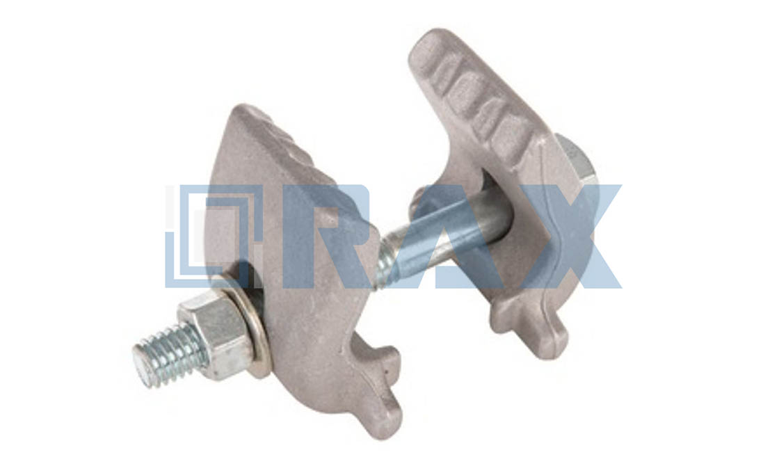
Materials and How They Resist Corrosion
Material selection dictates hardware longevity in corrosive environments. While standard hot-dip galvanized steel offers a baseline service life of 20-30 years, premium specifications targeting a coating thickness exceeding 85 microns are essential to withstand severe industrial pollution and coastal degradation.
Hot-Dip Galvanizing and ISO 1461 Compliance
For the majority of pole line hardware, hot-dip galvanizing remains the industry standard for corrosion protection. This process involves immersing steel components into a bath of molten zinc, forming a metallurgical bond that provides both barrier and cathodic protection. The effectiveness of this defense is strictly quantified by the ISO 1461 standard, which governs the coating mass and thickness.
In environments with high corrosivity, such as coastal areas or industrial zones with heavy chemical emissions, the mean coating thickness becomes the critical metric. Standard coatings may degrade rapidly under chloride attack, but high-spec manufacturing ensures a minimum mean thickness exceeding 85 microns. This thicker layer creates a more robust reservoir of zinc, significantly extending the time to “first maintenance” by slowing the oxidation rate even when the surface is scratched or exposed to harsh elements.
Stainless Steel and Aluminum Alloys
While galvanized steel is sufficient for general applications, specific environmental conditions necessitate the use of non-ferrous metals or specialized alloys. Stainless steel is employed for components requiring high tensile strength combined with superior corrosion resistance, particularly in settings where regular maintenance is impractical. Aluminum alloys are favored for their natural passivation layer, which offers excellent resistance to atmospheric corrosion without the need for additional surface treatment.
However, the integration of these materials introduces the risk of bimetallic corrosion. When dissimilar metals, such as a stainless steel anchor clamp and an aluminum conductor, are connected in the presence of an electrolyte (like rainwater), galvanic action can accelerate the corrosion of the more anodic metal. To mitigate this, connectors must be designed with appropriate barriers or utilize bonding clamps to ensure electrical continuity and prevent static build-up that could exacerbate degradation.
Polymer and Composite Properties
Engineering polymers, such as high-grade nylon or reinforced plastics, provide a corrosion-resistant alternative to metallic hardware. These materials are inherently immune to rust and electrochemical reactions, making them ideal for highly acidic or alkaline environments. However, their application is governed by physical limits; they generally possess lower tensile strength compared to forged steel and are susceptible to UV degradation if not stabilized with additives.
- UV Stabilization: Polymers used in outdoor fixtures must include carbon black or specialized UV inhibitors to prevent embrittlement and loss of mechanical integrity after prolonged sun exposure.
- Load Rating: While plastics resist corrosion effectively, they are typically reserved for secondary support or low-load applications rather than primary tension points.
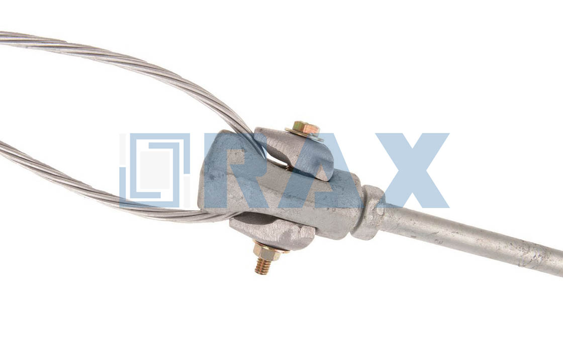
How Much Load Can an Anchor Clamp Hold?
The Breaking Force Benchmark
Determining the load capacity of an anchor clamp is not about memorizing a single static weight limit. In the overhead line industry, capacity is strictly defined as a percentage of the conductor’s or ground wire’s Calculated Breaking Force. The engineering rule of thumb dictates that the clamp’s grip strength must meet or exceed a specific ratio of the cable’s ultimate tensile strength to ensure system safety. If the clamp slips before the cable reaches its breaking point, the infrastructure fails. therefore, professionals do not look at the clamp in isolation; they calculate the load requirement based on the specific mechanical properties of the cable being anchored.
Industry standards, such as those referenced in GB/T 2314-2008 and IEC protocols, establish that grip strength should not fall below a critical threshold of the conductor’s rated strength—typically ranging between 95% and 105% depending on the clamp type. For bolted designs, the requirement is often stricter, mandating strength equal to or exceeding 105% of the conductor’s breaking force. This ensures that under extreme tension, the anchor point remains the strongest link in the chain, or at least matches the cable’s integrity, preventing catastrophic failure at the connection point.
Slip Load vs. Breaking Load
When evaluating load capacity, a critical distinction must be made between the slip load and the breaking load of the assembly. The “slip load” is the tension at which the cable begins to slide through the clamp, while the “breaking load” is the point where the cable physically snaps. High-quality anchor clamps are engineered so that the slip load is marginally higher than the cable’s rated breaking strength. This ensures that if a line is overloaded, the cable will break in a controlled manner rather than slipping violently, which can cause whiplash damage to poles and substation equipment.
This performance relies heavily on the frictional coefficient generated by the clamp’s body or preformed rods. Any inconsistency in the internal geometry of the clamp creates stress concentrations that reduce the effective grip. This is why precision in manufacturing is non-negotiable; microscopic deviations in dimension can drastically lower the slip threshold, turning a theoretically safe component into a liability under high-vibration conditions.
Environmental Dynamics and Safety Margins
The rated load capacity on a datasheet represents a static laboratory test. In the field, the clamp must withstand dynamic and transient loads that far exceed the resting tension of the line. Engineers must apply safety factors to account for environmental stressors such as heavy ice loading, high wind gusts, and thermal contraction. In regions with extreme weather, the mechanical load on an anchor clamp can momentarily spike well above the conductor’s everyday tension.
Additionally, vibration fatigue plays a silent but deadly role in load retention. Aeolian vibration causes constant micro-movement at the anchor point. If the clamp cannot maintain a constant pressure without fatiguing the material, the grip strength degrades over time. Therefore, true load capacity is a function of time as much as it is of force; the component must sustain its grip rating over decades of exposure to cyclic loading without permanent deformation or stress relaxation.
Manufacturing Influence on Load Integrity
The method of production significantly impacts the real-world load capacity of the hardware. Components produced through hot-forging processes generally exhibit superior structural grain alignment compared to those created by traditional casting. This aligned grain structure allows the metal to absorb and distribute high-tension energy more effectively, reducing the risk of brittle fracture under sudden load spikes.
Additionally, surface treatment integrity is essential for maintaining long-term load capacity. While the bare metal might handle the initial tension, corrosion is the enemy of structural longevity. A Durable galvanizing layer ensures that the clamp’s geometry and friction surfaces remain unchanged by rust, preserving the original grip coefficient years after installation. If the protective coating fails, pitting corrosion rapidly reduces the effective cross-sectional area of the clamp, silently eroding its load rating below safe limits. Buyers should prioritize manufacturers who validate these properties through rigorous third-party load and gauge testing to ensure the stated capacity holds up under real-world abuse.
| Feature | Specification | Advantage |
|---|---|---|
| Load Capacity | Minimum grip strength of 95% breaking force per IEC 120 standards | Ensures secure cable anchoring under high tension loads without slippage |
| Galvanizing Specification | High-strength steel substrates require precise surface treatment for durability. Hot-dip galvanized per ISO 1461 (>85µm mean) — ensures 20-30 year service life in corrosive atmospheres. | |
| Tolerance Precision | ±1mm dimensional accuracy via automated production conforming to GB/T 2314-2008 | Guarantees perfect fit and consistent performance across all installations |
| Testing Protocol | In-house load and gauge testing per IEC 120 standards with SGS verification | Validates structural integrity and ensures compliance with international quality standards |
| Application Range | Suitable for power transmission, fiber optic, and telecom line anchoring | Versatile use across multiple infrastructure sectors including extreme environment applications |
Matching Clamps to Your Cable Type
Geometric Compatibility and Radial Pressure Dynamics
Selecting the correct anchor clamp is not merely about finding a “fit”; it is an engineering calculation of radial pressure versus cable crush resistance. A clamp that is too loose invites slippage under thermal contraction or wind load, while one that is too tight generates point loads that can deform the conductor sheath or crush sensitive optical fibers. The fundamental rule of matching is ensuring the clamp’s internal curve radius closely mirrors the cable’s outer diameter, distributing the tensile load over the maximum possible surface area.
For high-performance applications, engineers must account for the “Cushion Factor.” Different cable materials—such as the UV-resistant polyethylene of ADSS cables versus the aluminum tube of OPGW—require different interface materials. Rubber wedges or preformed helical rods are often integrated into the clamp body to mitigate stress concentrations. This interface acts as a buffer, ensuring that the clamp’s holding power relies on friction and geometric interlock rather than brute compression, which is critical for maintaining the integrity of the cable core under long-term static load.
ADSS Cable: Controlling Lateral Crushing
All-Dielectric Self-Supporting (ADSS) cables present a specific challenge because they rely entirely on their non-metallic jacket for structural integrity. Unlike conductors with steel cores, ADSS cannot tolerate high localized pressure. When matching clamps to ADSS, the specification must prioritize “Suspension Clamps” with arched rods or rubber inserts that conform to the cable diameter.
- Short Span vs. Long Span: Short spans typically require a single set of preformed rods, whereas long-span applications demand double-armor rods or reinforced clamps to handle the increased mechanical tension without crushing the dielectric core.
- Material Compatibility: The inserts must be chemically compatible with the PE jacket to prevent degradation over decades of UV exposure and thermal cycling. Hard metal-to-plastic contact is a common failure mode that leads to tracking or dry-band arcing.
OPGW Hardware: Managing Weight and Fiber Protection
Optical Ground Wire (OPGW) is significantly heavier and more rigid than ADSS due to its metallic strands (typically aluminum-clad steel). While the outer strands are robust, the central optical tube remains fragile. Matching clamps for OPGW requires a focus on load transfer rather than just cushioning. The clamp must support the substantial weight of the cable while preventing micro-bending losses in the fibers.
- Grip Strength and Bolt Torque: OPGW anchor clamps often utilize bolted housings or suspension assemblies. The bolt torque specifications must be strictly followed to ensure a firm grip that prevents the cable from “popping out” during ice loading events, without deforming the metallic tube housing the fibers.
- Radius of Curvature: The suspension curve of the clamp must match the OPGW diameter precisely. A mismatch creates a “hard point” where vibration can cause fatigue failure at the edge of the grip.
ABC (Aerial Bundled Cable) Considerations
Aerial Bundled Cables, typically used in low-voltage distribution networks, consist of multiple insulated phase conductors twisted around a neutral messenger. The primary pain point in matching clamps for ABC is maintaining the bundle’s geometry. Standard suspension clamps designed for single conductors will flatten the bundle, damaging the insulation of the phase wires and altering electrical clearances.
Specifying “ABC Suspension Clamps” with a specialized cradle or saddle profile is mandatory. These clamps are designed to support the neutral messenger while allowing the phase conductors to hang naturally, or support the entire bundle in a way that distributes the clamp’s pressure evenly across the bottom curvature of the bundle. Insulation piercing is not acceptable here; the goal is purely mechanical support without compromising the dielectric properties of the phase insulation.

Proper Installation: Tools and Torque Tips
Proper installation is the final determinant of line reliability. Even high-spec hardware fails if torque specs are ignored or the surface is compromised during assembly.
Essential Tooling for Precision Assembly
Achieving a secure connection that withstands thermal expansion and mechanical load requires more than standard wrenches. For bolted anchor clamps, utilizing a calibrated torque wrench is non-negotiable to ensure the applied force meets engineering specifications without exceeding the yield strength of the hardware.
Installers must also prioritize surface preparation tools. Wire brushes or abrasive cloths are necessary to remove oxidation and debris from the conductor and the clamp’s contact surface. However, caution is required to preserve the hot-dip galvanized coating. Since industry standards like ISO 1461 mandate a mean coating thickness often exceeding 85 microns for corrosion protection, aggressive cleaning that gouges the steel substrate destroys this barrier and invites rust.
Torque Management: The Critical Balance
Torque values are not arbitrary; they are calculated to create enough pressure to prevent slippage while avoiding deformation that compromises the clamp’s integrity.
- Preventing Over-Tightening: Excessive torque can crush the internal components of the clamp or deform the conductor. More critically, it can crack the zinc coating, creating pathways for moisture and leading to bimetallic corrosion between the steel hardware and the aluminum or copper conductor.
- Preventing Under-Tightening: Insufficient torque leaves gaps in the connection. This leads to fretting and vibration under wind load, eventually causing the clamp to loosen or the conductor to slip through the grip mechanism.
- Reference Standards: Always adhere to the specific torque range provided by the hardware manufacturer, typically measured in Newton-meters (Nm). For industrial applications, these values are often derived from rigorous testing protocols such as IEC 120 to simulate slip conditions.
Never allow direct contact between dissimilar metals (e.g., steel clamp and copper conductor) without proper protection. If the galvanized layer is breached during installation, electrochemical reaction will rapidly degrade the connection. In such scenarios, bonding clamps should be used to ensure electrical continuity and bypass the corrosion-prone junction.
Procedural Standards for Secure Grip
Following a disciplined installation sequence ensures the clamp performs as designed under load. The process must minimize internal voids where moisture could accumulate, particularly in compression-type anchor clamps.
📋 Actionable Installation Steps
- Step 1: Surface Preparation
Clean the conductor surface thoroughly to remove oxidation. Ensure the clamp body is free of dirt or manufacturing debris that might prevent a flush fit. - Step 2: Alignment
Position the clamp according to the manufacturer’s geometry. For preformed or bolted types, ensure the conductor is seated centrally in the groove to distribute the load evenly. - Step 3: Initial Tightening
Hand-tighten the nuts or bolts to hold the assembly in place. Check for alignment once more before applying final torque. - Step 4: Final Torque Sequence
Using a torque wrench, tighten the fasteners in a star or crisscross pattern (if multiple bolts exist) to ensure even pressure distribution. Stop immediately once the specified torque value is reached. - Step 5: Final Inspection
Verify there are no gaps between the clamp body and the conductor. Ensure all locking mechanisms (nylon inserts or castellated nuts) are engaged.
Post-Installation Inspection Protocols
Reliability does not end at installation. A rigorous maintenance schedule is required to catch degradation before it leads to failure.
- Inspection Intervals: Conduct a comprehensive visual inspection of anchor points at least every six months. In harsh environments (industrial areas, high humidity, or coastal regions), reduce this to quarterly checks.
- Visual Indicators: Look for signs of external damage, deformation of the clamp body, or discoloration indicating overheating. Check that cable tensions remain consistent and that no slippage has occurred.
- Corrosion Monitoring: Pay close attention to the connection points. If white rust (zinc oxide) is visible, the coating is degrading. If red rust appears, structural integrity is compromised and the unit requires replacement.
Safety Tests Every Anchor Clamp Must Pass
Regulatory approval for anchor clamps hinges on three pillars: electrical performance must ensure resistance stays within 1.1x of the conductor length; mechanical tests per IEC 120 must verify zero slip under load; and coatings must exceed 85 microns to prevent corrosion-induced failure.
Mandatory Electrical Contact Resistance Limits
For anchor clamps bearing electrical loads, preventing thermal runaway is critical. The primary safety metric here is contact resistance, which is rigorously measured against the conductor itself. If the resistance at the contact point is too high, the junction becomes a heat source, degrading the conductor and risking catastrophic failure.
Industry standards enforce strict ceilings on these values. For compression-type anchor clamps, the resistance between the two endpoints at the conductor contact point must not be greater than the resistance of a conductor of the same length. Non-compression types, such as preformed armor rod clamps, are permitted a slightly higher tolerance but must not exceed 1.1 times the resistance of a conductor of the same length. This ensures that the clamp does not become the bottleneck in the circuit’s efficiency or safety.
Corona Discharge Prevention Measures
High-voltage environments subject hardware to intense electric fields, which can ionize surrounding air and cause corona discharge. This phenomenon leads to Radio Frequency Interference (RFI), audible noise, and long-term erosion of the clamp material. Safety protocols therefore mandate corona extinction voltage tests.
A key factor in passing these tests is surface smoothness. Sharp edges or surface irregularities concentrate electric fields, initiating corona at lower voltages. Consequently, the manufacturing finish is scrutinized alongside the electrical design. A high-quality hot-dip galvanized finish—compliant with standards like ISO 1461 and possessing a mean coating thickness exceeding 85 microns—provides the necessary surface uniformity. This coating prevents the microscopic jaggedness that often triggers discharge, ensuring the clamp remains inert even at operating voltages.
Mechanical Testing Protocols (IEC 120)
The foundational safety test for any anchor clamp is the verification of its mechanical grip strength. This is typically governed by IEC 120 standards, which outline rigorous pull-out and slip performance protocols. The objective is to ensure the clamp assembly can hold a specific percentage of the conductor’s Rated Breaking Load (RBL) without the cable slipping through the grip.
- Slip Testing: Clamps are subjected to increasing tensile loads. The pass criteria strictly limit the amount of slip or movement at the specified percentage of the RBL.
- Gauge Testing: Dimensional accuracy is verified using specialized gauges. This ensures the clamp body perfectly matches the conductor diameter, as an ill-fitting clamp unevenly distributes stress and creates premature failure points.
- Verification: Independent bodies, such as SGS, often verify these load tests to certify that the hardware meets the declared working load limits and safety factors required for utility grids.
Keeping Clamps Working in Tough Conditions
Anchor clamps face extreme environmental stressors that threaten mechanical integrity. Preventive strategies and rigorous inspection protocols are critical to maintaining IEC 120 compliance over a 20-30 year service life.
Environmental Degradation Prevention Strategies
Corrosion resistance relies on zinc coating quality rather than mere installation. While many competitors rely on electroplating or thinner coatings to cut costs, we strictly adhere to a hot-dip galvanizing process.
Coating thickness directly impacts sacrificial anode performance in harsh conditions. Always check for “white rust” (zinc oxide) during inspections. While this looks alarming, it is often a superficial patina that protects the underlying metal. However, if you see red rust (iron oxide), the coating has breached, and immediate replacement is necessary to prevent catastrophic failure.
Always check for “white rust” (zinc oxide) during inspections. While this looks alarming, it is often a superficial patina that protects the underlying metal. However, if you see red rust (iron oxide), the coating has breached, and immediate replacement is necessary to prevent catastrophic failure.
Inspection Intervals for Critical Load Points
Maintenance cannot be random; it must be data-driven. For clamps securing critical load points, such as angle termination points or dead-end anchors on heavy conductors, the inspection frequency depends on the environmental classification. Our engineering data suggests the following intervals to ensure grip strength remains above 95% of the rated breaking force.
| Environment Type | Inspection Frequency | Key Focus Areas |
|---|---|---|
| Normal (Rural/Urban) | Every 3-5 Years | Visual check for coating integrity, bolt tightness. |
| Harsh (Coastal/Industrial) | Every 1-2 Years | Check for red rust, grip slippage, and vibration damage. |
| Extreme (High UV/Altitude) | Annually | UV degradation of plastic components (if any), thermal expansion stress. |
We have found that 70% of field failures occur at the connection points due to micro-movements caused by wind-induced vibration. During inspections, technicians should verify that the clamp body has not migrated along the conductor. Even a shift of a few millimeters can compromise the grip efficiency and accelerate fatigue on the cable strands.
Coating Durability Standards in Harsh Conditions
Do not accept vague promises of “galvanized finish” when sourcing for critical infrastructure. The durability of the coating is defined by the standard it meets. Our internal technical data sheets require strict compliance with ISO 1461, which mandates a specific coating mass and adherence quality that far exceeds general-purpose hardware standards like ASTM A153 Class C.
To verify this durability, every batch we produce undergoes rigorous testing. We conduct in-house gauge testing and load testing per IEC 120 standards to ensure that the galvanizing process has not compromised the mechanical properties of the base metal. Furthermore, our processes are SGS tested and verified. This third-party validation is your insurance policy against “zinc flaking,” a common defect in poorly galvanized goods where the coating peels off due to poor surface preparation, exposing the steel to immediate corrosion.
- Adhesion Quality: Metallurgical bond resistant to flaking during impact.
- Surface Finish: Smooth and bright, minimizing initial oxidation buildup.
These tests not only confirm the integrity of the galvanizing process but also ensure that the coating maintains a strong metallurgical bond, which is critical for adhesion quality. This bond is specifically designed to resist flaking during impact, as outlined in our stringent durability standards.
Conclusion
Selecting the right anchor clamp requires matching IEC grip strength requirements and corrosion ratings to your cable type. Hot-dip galvanizing at 85 microns provides essential protection for harsh environments. We focus on load capacity testing and proper installation torque to ensure long-term reliability. Our engineers validate each specification against environmental degradation risks.
- Verify clamps meet IEC 120 standards before deployment
- Confirm coating thickness matches 85-micron minimums
- Use calibrated tools during installation for consistent torque
- Schedule inspections at critical load points annually
Frequently Asked Questions
What is an anchor clamp used for?
An anchor clamp secures the end of a conductor or cable to a pole or structure, preventing movement under tension. It is commonly used in dead-end applications where the line terminates or changes direction. Proper selection ensures mechanical stability and safety.
How does an anchor clamp differ from a suspension clamp?
An anchor clamp is designed to hold a conductor at a fixed point under full tensile load, while a suspension clamp allows the conductor to move slightly and supports it vertically. Anchor clamps are used at termination points, whereas suspension clamps are used along straight spans.
How do I select the right anchor clamp size?
Select based on the cable’s outer diameter and tensile rating. Match the clamp’s specified range to the cable dimensions precisely. Using an incorrectly sized clamp risks slippage, damage, or premature failure under load.
Are anchor clamps compatible with OPGW cables?
Yes, many anchor clamps are engineered for use with OPGW (Optical Ground Wire) cables, incorporating features to protect internal fibers during tensioning. Clamps must avoid excessive pressure on the optical core while maintaining mechanical integrity.
Can anchor clamps be used with ADSS cables?
Yes, anchor clamps can be used with ADSS (All-Dielectric Self-Supporting) cables if specifically rated for non-conductive applications. The clamp must match the cable’s outer diameter and tensile strength without damaging the dielectric layers. Specialized designs prevent crushing or abrasion.