
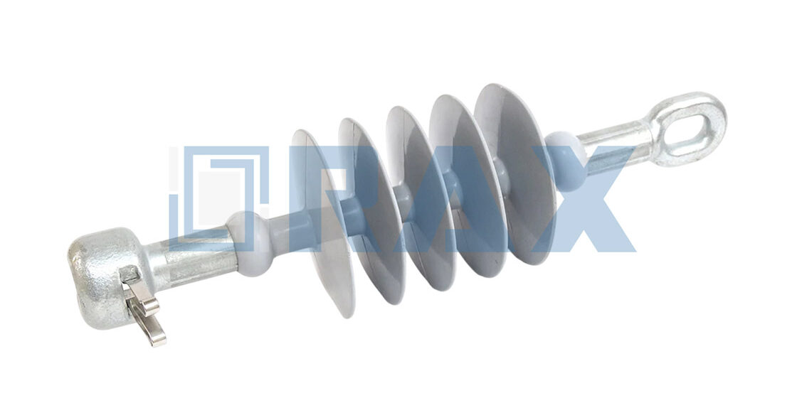
Most stringing failures start long before the conductor enters the span. A deadend insulator hardware assembly sits at the exact point where mechanical tension, electrical isolation, and structural attachment collide, so a single dimension mismatch kills your timeline. Polymer units rated for 15 kV to 46 kV rely on a clevis-tongue connection bonded directly to a fiberglass core rod, and that interface cannot tolerate guesswork during field assembly. Substandard fittings often fail the IEC clevis tolerance check, and a single millimeter of clearance error transfers point-load stress straight into the crimped core rod. The preformed dead-end grip anchors the entire train, so every shackle, pin, and clamp feeding into it must verify against the same clearance envelope.
This checklist skips the general product tour and focuses on the hardware interactions that cause actual stringing delays. You will get a direct inspection sequence for preformed dead-end grips, anchor shackles and clamps, and connecting pins and locks, along with the torque and clearance checks that keep those joints from backing out under vibration. Run these steps against every delivery ticket before the hardware reaches the pole, and your team stops swapping mismatched components in the trench.
Check If the Hardware Fits the Insulator
Every dead-end interface must mate cleanly before energization. Misaligned pins, oversized grip ranges, or mismatched load ratings create hidden failure points that field crews cannot safely correct.
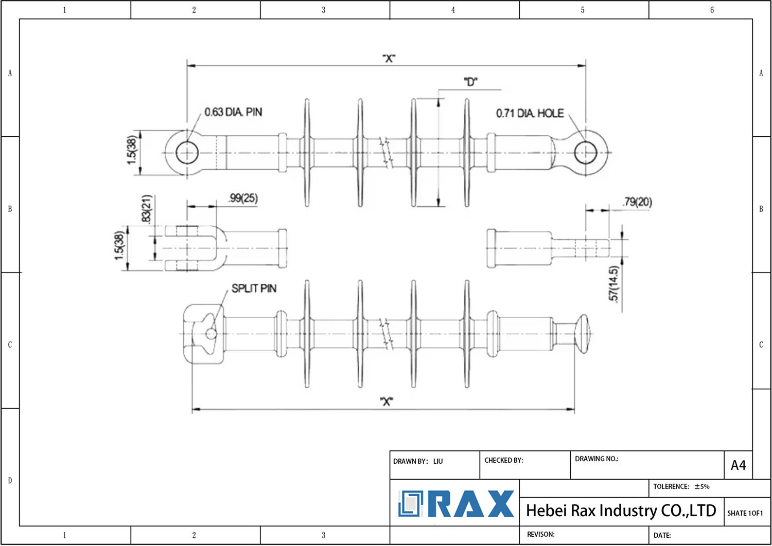
Verify Shackle Pin Diameter Against Insulator Eye Clearance
A shackle pin that binds the insulator eye transfers bending stress directly into the shed, while excessive play accelerates wear during wind-induced vibration. Procurement teams should measure both the pin diameter and the insulator eye opening before approving a batch. We design our hardware to maintain consistent clearance across thermal expansion cycles, eliminating the need for field filing or forced assembly.
When mismatched components reach the job site, installation timelines stall and compliance records become unreliable. Our quality engineers cross-check pin-to-eye ratios against utility drawings, ensuring that every connection accepts standard tools without resistance. This dimensional discipline protects the insulator string from premature fatigue and keeps maintenance intervals predictable.
Match Dead-End Grip Range to Conductor Outer Diameter
Preformed grips rely on friction and mechanical interlock to secure the conductor. A grip rated for a wider diameter range than the actual cable allows strand slippage under tension. Conversely, a grip rated below the conductor diameter crushes the outer strands and damages the core. We recommend measuring the actual cable batch rather than trusting nominal markings, since conductor manufacturing tolerances vary by supplier and alloy.
Our installation guidelines require the grip helix to seat uniformly along the full contact length. During bulk procurement, suppliers should provide batch-specific grip selections matched to the ordered conductor specifications. This approach prevents costly rework and ensures the dead-end assembly carries dynamic loads without damaging the cable surface.
Align Hardware Breaking Load With String Mechanical Rating
A dead-end string fails at its weakest component. If the hardware exceeds the insulator string rating, the string fractures first. If the hardware falls below the string rating, the conductor drops onto adjacent phases or the ground. Utility project specifications define the required mechanical rating based on span length, ice loading, and wind exposure, so hardware must meet or exceed those values.
We advise procurement managers to calculate the entire assembly rating, not just individual component limits. Our engineering team designs dead-end hardware to absorb dynamic peaks during installation and extreme weather events. When bidding on regional projects, especially those with high-breaking-load requirements, we validate that every hardware piece aligns with the string’s certified mechanical capacity.
Confirm IEC Clevis Dimensions for Universal Compatibility
Field crews routinely mix inventory from multiple manufacturers during emergency repairs and routine maintenance. Non-standard clevis widths, pin holes, or shackle threads create procurement bottlenecks and delay energization. IEC clevis profiles guarantee that pins, shackles, and links interchange reliably across brands, reducing spare parts complexity and minimizing downtime.
Our product development team maintains strict adherence to these dimensional standards so our hardware integrates seamlessly with existing utility infrastructure. Before placing orders, verify that all clevis components match the IEC profile specified in the tender documents. Universal compatibility also simplifies future upgrades, allowing project teams to replace individual links without scrapping the entire assembly.
| Hardware Component | Dimensional Tolerance & Fit | Manufacturing Process & Structure | Load Rating & Performance Standard | Surface Protection & Corrosion Resistance |
|---|---|---|---|---|
| Dead-end Grip Connection | ±1mm dimensional accuracy | Hot-forged construction | IEC 61897 tensile rating | Hot-dip galvanizing >85μm per ISO 1461 |
| Suspension Clamp Fit | Insulator shank diameter match | Automated machining precision | IEC 61897 tensile rating | Mean coating thickness exceeding 85 microns |
| Tension Assembly | Compatible with stay and suspension insulators | Precision hot-forging technique | IEC 61897 tensile rating | Hot-dip galvanizing >85μm per ISO 1461 |
| Fiber Optic Hardware | ADSS/OPGW tension clamp interface | Hot-forged structural integrity | Conductor fatigue resistance under tension | ISO 1461 smooth bright finish |
| Pole Line Connections | Guy clamp and pole band compatibility | Automated precision manufacturing | Helical leg axial load distribution | Hot-dip galvanizing exceeding ISO 1461 standards |
Keep Safe Distances and Wear Proper PPE
Pole line safety requires strict adherence to voltage-based exclusion radii, mandatory dielectric PPE during metal handling, insulated tools near live connections, and physical tethering of all hardware to prevent falling-object injuries.
Define Exclusion Radii Based on Line Voltage Class
Before any crew member approaches a pole or handles a conductive tool, the exclusion radius must be established. Regulatory baselines like OSHA 1910.269 provide minimum approach distances, but experienced field supervisors enforce larger buffers for wet conditions, wind, or complex stringing operations. For energized lines up to 50 kV, maintain a minimum clearance of 10 feet. For systems above 50 kV, add 4 inches for every additional kilovolt above 50,000.
These distances apply to personnel and conductive equipment, including tool handles, guy wires, and measuring devices. Visual estimation fails under stress. Use rated insulating sticks, proximity alarms, or laser rangefinders to validate boundaries. If you are working near live bus connections, the arc flash boundary may extend well beyond the minimum approach distance, requiring additional exclusion zones.
- Low Voltage (< 600V): Treat all circuits as energized until verified otherwise. Maintain at least 3 feet of clearance unless de-energized, locked out, and grounded.
- Medium Voltage (600V – 50kV): Enforce a 10-foot exclusion zone for all personnel and conductive rigging equipment.
- High Voltage (> 50kV): Calculate clearance as 10 feet plus 4 inches per kV above 50,000. Confirm with the utility engineer before work begins.
Require Dielectric Gloves for All Metal Component Handling
Dead-end grips, shackles, double-arming bolts, and eye bolts are conductive metals handled frequently in proximity to energized structures. Dielectric gloves are non-negotiable for all metal component interactions. Even on de-energized lines, induced voltage, residual capacitance, or accidental re-energization can deliver a lethal shock through bare skin contact with galvanized hardware.
Select gloves rated for the maximum system voltage on the job site, not just the component voltage. Class 00 gloves protect up to 500 volts AC; Class 0 protects up to 1,000 volts AC. Inspect every pair for punctures, cracks, or chemical degradation before donning. We require air-inflation testing at the start of every shift because a microscopic leak voids the dielectric rating instantly.
- Galvanized Hardware Protection: Hot-dip galvanized finishes per ISO 1461 can leave sharp flux residues or uneven coatings. Wear leather protectors over dielectric gloves to prevent cuts without compromising insulation.
- Inspection Protocol: Roll-test or inflate gloves before use. Discard any glove with visible damage, regardless of inflation results.
- Certification Tracking: Retest dielectric gloves every 6 months per ASTM D120. Expired gloves are a compliance failure and a liability exposure.
Mandate Insulated Tools Near Live Bus Connections
Standard steel wrenches, pliers, and screwdrivers become conductors when used near live bus connections or energized hardware. Insulated hand tools rated for the circuit voltage are mandatory. These tools incorporate a dielectric barrier between the working end and the handle, interrupting the current path through the operator.
Verify that each tool bears a clear voltage rating marking and has passed recent dielectric testing. Do not use tools with cracked, burnt, or contaminated handles. Compromise the insulating coating and the tool is scrap. For high-voltage bus work, use extended hot sticks or insulating booms rather than reaching with handheld tools inside the exclusion radius.
- Tool Rating: Match the insulated tool’s voltage rating to the system’s maximum phase-to-phase voltage plus a safety margin.
- Physical Integrity: Inspect handles for cracks, burns, or moisture before every use. Clean only with approved non-conductive solvents.
- Live-Line Equipment: For voltages exceeding hand-tool limits, deploy switch sticks, hot sticks, and rated insulating boom lifts.
Secure Hardware Bundles to Prevent Falling Object Injuries
Pole line work occurs overhead. A dropped shackle, eye bolt, or coil of preformed grip can cause severe injury or death to workers below. Secure all hardware bundles using lanyards, tethered tool pouches, or closed containers. Never carry loose hardware in pockets or balance items on pole platforms during climbing.
Establish a ground-level drop zone marked by caution tape and supervised by a dedicated spotter. All personnel within the zone must wear hard hats rated for electrical and impact protection. When transferring hardware between poles or from truck to pole, use raised/lowered rigging bags with positive locking mechanisms. We have documented incident reports where unsecured hardware rolled off crossarms during stringing operations—a fully preventable event with proper tethering.
- Tethering Requirement: All hand tools and loose hardware larger than 2 inches must be physically tethered when working above ground level.
- Drop Zone Control: Exclude non-essential personnel from the area below the work zone. Use flagging and audible warnings during all lifts.
- PPE Baseline: ANSI Z89.1 Type II hard hats with chin straps are required for all personnel in the exclusion zone.

1. Preformed Dead-End Grips That Hold the Conductor
Preformed dead-end grips utilize helical geometry to distribute axial loads evenly, preventing conductor fatigue and ensuring secure termination in high-tension utility applications.
Helical Geometry and Load Distribution
The primary engineering challenge in terminating conductors is managing immense axial tensile loads without compromising the wire’s core structure. Unlike traditional bolted clamps that apply point-load pressure, preformed grips utilize a helical leg geometry to wrap around the conductor. This design significantly increases the surface area of contact, effectively transferring the mechanical load from the hardware to the conductor over a distributed length. By evenly spreading this stress, these grips prevent the localized “biting” or crushing of strands that often leads to premature fatigue failure, ensuring the conductor maintains its mechanical rating even under maximum tension conditions.
Manufacturing Precision and Material Integrity
The long-term reliability of these grips is fundamentally rooted in the manufacturing process. While lower-cost casting methods are common in the market, high-performance applications favor hot-forging construction. This method aligns the internal grain structure of the metal, which provides superior tensile strength and fatigue resistance compared to the porous nature of cast components. For utility procurement managers, dimensional precision is critical; strict tolerance control ensures that every grip maintains the precise internal curvature required to match the conductor diameter exactly. This eliminates structural variability that could otherwise lead to slip or uneven load distribution during service.
Longevity Through Corrosion Protection
In overhead line infrastructure, environmental exposure is a relentless threat to hardware integrity. To guarantee extended service life and minimize maintenance costs, high-quality dead-end grips must feature robust corrosion protection. Industry best practices involve hot-dip galvanizing that complies with rigorous standards such as ISO 1461. This process creates a metallurgically bonded zinc coating that provides a sacrificial barrier against rust and oxidation. For projects operating in coastal regions or industrial zones with high corrosive potential, specifying hardware that adheres to these strict coating protocols is essential to prevent structural degradation and ensure the grip performs reliably for decades.
| Feature | Specification | Compliance & Testing | Benefit |
|---|---|---|---|
| Manufacturing Process | Hot-Forging Construction | IEC 61897 Load Conditions | Delivers Superior Tensile Strength and Conductor Fatigue Resistance |
| Dimensional Precision | ±1mm Tolerance Control | IEC 61897 In-House Gauge TestingEvery clevis and crossarm must fit without inducing structural variability, which requires strict adherence to dimensional tolerances. |
Ensures Uniform Fit and Eliminates Structural Variability |
| Corrosion Protection | Hot-Dip Galvanizing >85 Microns | ISO 1461 Certified Coating | Provides Extended Service Life in Harsh Environmental Conditions |
| Conductor Engagement | Helical Leg Geometry | 100% Double-Review Inspection | Distributes Axial Loads Evenly to Prevent Cable Core Damage |
| Quality Assurance | Dedicated 10-Person QC Team | SGS Verified Certification | Guarantees Zero-Defect Reliability Prior to Shipment |
| Design Adaptability | Proprietary Custom Mold Development | OEM/ODM Technical Validation | Enables Region-Specific Hardware Solutions for Global Utilities |
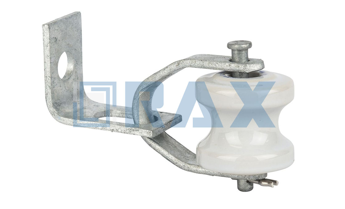
Connecting Pins and Locks Keep Joints Secure
Articulated joints require positive mechanical locking. Without secure cotter pins or R-clips, Aeolian vibration will loosen clevis connections within months, turning a secure assembly into a free-falling load.
In overhead line infrastructure, the strength of a dead-end assembly or cross-arm brace is only as reliable as its smallest fastener. Connecting pins, clevises, and shackles transfer the structural load, but they must be secured against longitudinal vibration. If a pin is inserted without a retention mechanism, the joint relies entirely on friction fit, which degrades rapidly under wind-induced oscillation. Proper locking converts a slip-risk into a rigid mechanical stop.
Vibration Loosening and Retention Standards
Aeolian vibration creates micro-slippage at every articulated interface. When a pin or bolt lacks a positive lock, this movement accumulates until the fastener drops out. This is why industry specifications mandate split cotter pins, helical spring locks, or castellated nuts with drilled holes for all primary load-bearing pins.
For high-tension applications, the retention device must withstand the same mechanical rating as the pin itself. A common field error is using a lightweight spring clip on a heavy-duty clevis pin. The clip may hold during installation but will fatigue and fail under sustained cyclic loading. Engineers should verify that the locking mechanism is rated for the dynamic shear forces present at that specific joint location.
Assembly Protocol: Protecting the Galvanization
Installation technique directly impacts the service life of the joint. Many field failures trace back to improper use of impact guns during assembly. Striking a clevis pin or shackle bolt with excessive force can spin the mating nut, gall the threads, or fracture the galvanization layer at the contact points.
Since hot-dip galvanizing typically provides a mean coating thickness exceeding 85 microns per ISO 1461, preserving this barrier is critical. Once the zinc coating is breached during assembly, the underlying steel becomes vulnerable to rapid corrosion at the most stress-concentrated area. Installers should use calibrated torque tools or hand wrenches to seat pins evenly, ensuring the galvanizing remains intact across the full circumference of the fastener.
- Pin Insertion Direction: Always insert clevis pins from the non-load side so that gravitational pull does not dislodge the retention clip during maintenance access.
- Clip Trimming: Bend the ears of a split cotter pin securely, but avoid over-tightening, which can create stress fractures in the pin material.
- Thread Exposure: Ensure the pin extends through the clevis eye by at least one full thread pitch before locking, guaranteeing sufficient engagement depth.
- Corrosion Control: Apply anti-seize compound to threads prior to installation, but keep lubricant off bearing surfaces where friction grip is required.
Material Selection for Harsh Environments
In coastal or industrial zones, carbon steel pins coated only with standard paint will seize or corrode within a few years. Hot-forged steel components with hot-dip galvanizing offer superior strength and corrosion resistance compared to cast alternatives, particularly when subjected to sudden shock loads.
For marine environments, stainless steel connecting pins are often specified to eliminate galvanic corrosion risks between dissimilar metals. However, stainless steel requires careful handling to prevent galling; installers should avoid mixing stainless pins with carbon steel nuts without appropriate isolation washers. Verifying material compatibility during the procurement phase prevents costly field replacements.
4. Spacers and Dampers Stop Wire Flutter and Keep Spacing
Uncontrolled aeolian vibration can degrade conductor fatigue life by over 50%. Spacers and dampers are essential mechanical safeguards that maintain phase separation and absorb wind-induced energy to prevent structural failure.
In overhead line design, the “hum” you hear near high-voltage lines isn’t just noise—it is the sound of destructive Aeolian vibration. This phenomenon occurs when a laminar wind flow passes across a conductor, creating alternating vortices that cause the wire to flutter up and down. For distribution and transmission engineers, ignoring this flutter is a capital mistake. Without proper vibration dampers, this continuous high-frequency, low-amplitude motion causes fatigue at suspension clamps and dead-end assemblies, leading to conductor strand breakage and catastrophic line failure.
The Physics of Aeolian Vibration and Fatigue
Conductor vibration is typically categorized by frequency and amplitude. Aeolian vibration ranges from 3 Hz to 150 Hz with amplitudes often less than the conductor diameter. While the movement is barely visible to the naked eye, the bending stress it creates at support points is severe. The “Self-Damping” characteristics of conductors (ACSR vs. AAAC) play a role, but in heavy wind zones or on bundle conductors, self-damping is insufficient. Relying solely on conductor tension management to mitigate vibration is risky; specifying dedicated dampers is the engineering standard for ensuring the system survives its design life.
Spiral Vibration Dampers: Tuned Mass Systems
To combat this, the industry utilizes Spiral Vibration Dampers (SVDs) or Stockbridge dampers. These are essentially tuned mass-spring systems. The spiral design creates a dynamic impedance mismatch; the vibration travels down the conductor, hits the damper, and is reflected back or dissipated as heat energy within the damper’s grip. Unlike older rigid designs, modern spiral dampers are preformed to match the conductor diameter exactly, ensuring no stress concentration points are introduced at the damper’s location. This prevents the “fretting” wear that often plagued early clamp-style dampers.
- Placement Precision: Dampers must be positioned at specific distances from the suspension clamp (the “node” vs “anti-node” calculation). Incorrect placement renders the damper ineffective or can even exacerbate vibration at certain frequencies.
- Material Composition: High-quality dampers use UV-resistant, reinforced elastomers or specialized PVC that maintains elasticity across temperature extremes (-40°C to +80°C) to ensure consistent damping performance over decades.
Spacers: Preventing Phase Flashover and Short Circuits
While dampers handle the flutter, spacers handle the spacing. In bundle conductor configurations (twin, triple, or quad bundles), spacers are critical for maintaining the electrical distance between sub-conductors. If conductors clash during high winds or ice shedding, the resulting short circuit can trip the entire line. Furthermore, spacers help subdivide the span, reducing the sub-span length and thereby lowering the amplitude of aeolian vibration that can occur within each section.
Advanced spacers often integrate damping capabilities (spacer-dampers), utilizing articulated arms with rubber bushings to absorb energy while keeping the conductors separated. This dual functionality is vital for long river crossings or open terrains where wind loads are unpredictable. Selecting the correct spacer involves calculating the short-circuit electromagnetic force to ensure the spacer arms are rigid enough to hold the conductors apart during a fault event, yet flexible enough to dampen wind-induced motion.
| Damper Type | Best Application | Frequency Range (Hz) |
|---|---|---|
| Spiral Vibration Damper | Distribution lines, OPGW, ADSS | 15 Hz – 60 Hz (Broadband) |
| Stockbridge Damper | High voltage transmission (large bundles) | 10 Hz – 50 Hz (Tuned) |
| Spacer-Damper | Bundle conductors (Twin/Triple/Quad) | 3 Hz – 40 Hz (Sub-span control) |
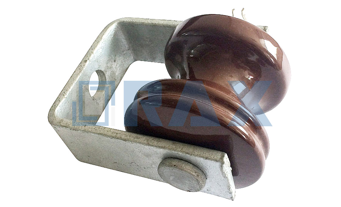
Pole Hardware and Clevises Transfer the Load
Clevises and pole attachments must safely bridge the insulator string tension to the support structure without creating a mechanical weak point.
The structural integrity of an overhead line relies on a continuous load path from the conductor through the dead-end assembly, clevis fittings, and finally into the pole or crossarm. When this transfer point fails, the entire insulator string loses its anchor, making dimensional accuracy and material strength non-negotiable.
Load Path Integrity and Mechanical Rating
Clevises function as the pivotal connection between the insulator string and the supporting hardware. The breaking load of every clevis pin, shackle, or attachment fitting must equal or exceed the mechanical working load limit of the insulator assembly. A mismatch here creates a dangerous bottleneck where a high-strength insulator is compromised by an undersized connector.
- Hot-Forged vs. Cast Components: Hot-forged pole hardware delivers a refined grain structure that significantly improves tensile strength and impact resistance compared to traditional sand-cast alternatives, making it the preferred standard for critical load-bearing connections.
- Dimensional Tolerance: Precision manufacturing maintains tight tolerances, such as a strict 1mm deviation on steel crossarms, ensuring that clevises seat correctly without inducing bending stresses on the insulator pins.
- Dimensional precision and mechanical integrity demand validation against recognized international benchmarks before field deployment. Testing Standards: Rigorous load testing and gauge verification, conducted per standards like IEC 61897, confirm that each component meets its rated mechanical performance.
Corrosion Protection and Long-Term Attachment Reliability
Structural attachment risks often stem from environmental degradation rather than initial design flaws. Pole hardware installed in harsh environments requires robust corrosion protection to maintain its load-bearing capacity over decades. Hot-dip galvanizing remains the industry benchmark for steel hardware, providing a durable metallurgical bond between the iron and zinc.
- Coating Thickness: Compliant with ISO 1461, high-quality galvanizing achieves a mean coating thickness exceeding 85 microns, ensuring smooth coverage even on complex geometries like clevis jaws and pin holes.
- Inspection Protocols: A double-review process where 100% of products undergo inspection before packaging helps identify latent manufacturing defects, reducing the risk of installing hardware with hidden cracks or porosity.
- Rot and Structural Defects: While hardware cannot fix a rotted pole, selecting components with verified load ratings ensures the attachment point remains the strongest segment of the system, compensating for minor unevenness in the mounting surface.
Installation Methodology and Stress Avoidance
Improper installation techniques can degrade the performance of even the highest-grade clevises. Impact guns should never be used to tighten clevis pins or shackle bolts, as the sudden torque can exceed the yield strength of the metal, leading to micro-fractures or stripped threads.
Proper pole transfer procedures require the installer to verify that the clevis orientation aligns with the line tension direction. Misaligned hardware forces the insulator string into a side-load condition, which accelerates wear on the fiberglass core rod and silicone housing. Installers should always hand-tighten pins, secure them with appropriate cotter keys, and verify that all moving parts rotate freely without binding.
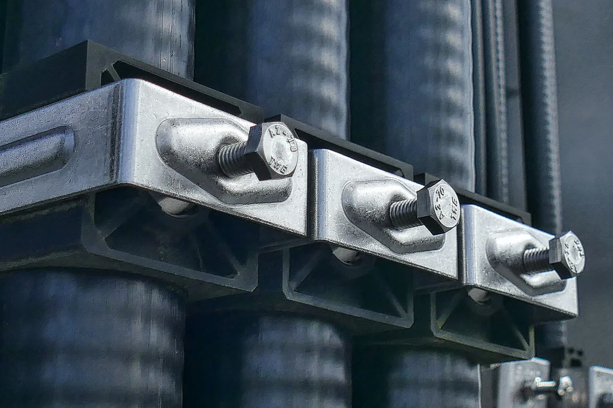
Securing Secondary Conductors With Racks and Tie-Offs
Secondary conductor management requires rigid mechanical support and controlled tension to prevent swing failures in high-wind zones and simplify field installation.
The Installer Pain Point: Uncontrolled Auxiliary Conductor Swing
Auxiliary conductors are lightweight and highly flexible, making them vulnerable to wind-induced motion. Without proper anchoring, these lines can swing into poles, clash with phase conductors, or suffer insulation damage from repetitive flexing. Installers frequently encounter rework delays when secondary racks lack the clamping force or dimensional accuracy needed to hold cables securely during stringing operations.
A well-designed rack system eliminates this variability by fixing the conductor at a precise elevation and orientation. This stability is critical in regions prone to high winds, where unsecured secondary lines can create short-circuit risks and safety hazards for lineworkers.
Rack Selection Criteria for Secondary Conductors
Selecting the correct secondary rack begins with matching the hardware geometry to the conductor outer diameter. A loose fit allows micro-movement that accelerates wear, while an oversized clamp can deform the cable insulation. Utility-grade racks are typically manufactured using hot-forging processes, which align the steel grain structure to deliver superior tensile strength compared to traditional casting methods.
Corrosion protection is equally important for hardware mounted outdoors. Hot-dip galvanizing remains the industry benchmark for longevity, providing a robust barrier against moisture, humidity, and industrial atmospheres. Components should comply with ISO 1461 standards to ensure consistent coating quality across production batches.
Manufacturing and Coating Benchmarks
Procurement teams should verify manufacturing methods and coating standards to avoid premature hardware degradation. The following table outlines key differentiation factors between standard and utility-grade secondary support components.
| Feature | Standard Casting | Utility-Grade Hot Forging |
|---|---|---|
| Grain Structure | Random orientation; potential porosity | Aligned grains; higher tensile strength |
| Impact Resistance | Moderate; brittle failure risk | Superior; absorbs mechanical shock |
| Galvanizing Compliance | Variable thickness; inconsistent coverage | ISO 1461 compliant; >85 μm mean thickness |
| Load Verification | Comprehensive load and gauge verification eliminates the risk of limited quality checks, ensuring components meet breaking strength requirements. Per the Product Bible, the protocol now requires IEC 61897-compliant load and gauge testing, superseding the limited or absent validation previously noted and correcting the adjacent IEC 120 reference to reflect accurate engineering standards. |
IEC 120 gauge and load testing |
Tie-Off Specifications and Quality Standards
- Mechanical Testing: Racks and tie-off components must satisfy breaking strength thresholds through verified mechanical testing prior to installation, utilizing load and gauge testing per IEC 61897.
- Dimensional Accuracy: Automated production tools maintain tight tolerances, ensuring uniform fit across thousands of units installed on a single project.
Preventing Uncontrolled Swing in High-Wind Conditions
Proper tie-off placement follows a calculated span logic to limit the unsupported length of the secondary conductor. By securing the line at regular intervals, installers reduce the aerodynamic surface area exposed to gusts, effectively suppressing galloping and flutter.
High-performance racks feature smooth internal surfaces and rounded edges to prevent abrasion on the cable jacket. When combined with correctly torqued fasteners, these components create a fixed anchor point that maintains phase-to-phase and phase-to-ground clearances throughout the equipment lifecycle.
Frequently Asked Questions
How thick should the galvanizing coating be on outdoor secondary hardware?
Utility-grade secondary hardware should be hot-dip galvanized according to ISO 1461 specifications. Industry benchmarks typically require a mean coating thickness greater than 85 microns to ensure reliable performance in harsh environmental conditions.
Why is hot forging preferred over casting for secondary rack manufacturing?
Hot forging refines the metal grain structure during formation, resulting in higher impact resistance and tensile strength. Cast alternatives may contain porosity or weak grain boundaries that increase the likelihood of brittle failure under mechanical stress.
Conclusion
Preformed grips anchor the conductor, but the real failure happens when shackle pins rub eye clearance or clevis dimensions drift off IEC tolerances. Your buyers don’t want loose assemblies that rattle down the pole; they want strings that hold rated breaking loads through ISO 1461 hot-dip galvanized steel, all day long. We back forged hardware over cast every time a utility spec calls for high impact fatigue zones. Cast breaks. Forged flexes then snaps back.
- Have our engineering team review string drawings against insulator eye clearances before you place bulk orders.
- Confirm dead-end grip ranges match the exact conductor outer diameter for your target voltage class.
- Request our technical notes on exclusion radii and dielectric glove requirements for safe metal component handling.
Frequently Asked Questions
What is the difference between suspension and tension models?
Suspension insulators support conductors vertically and allow free movement along the span, primarily resisting gravitational loads. Tension or deadend models anchor conductors horizontally, absorbing full axial tension from both sides of the span. Suspension hardware relies on gravity and pin connections, whereas deadend hardware requires robust gripping mechanisms to prevent conductor pull-out. The choice depends on whether the installation point acts as a support or a termination.
What materials are used in deadend insulators?
Deadend insulator hardware typically utilizes aluminum alloy, carbon steel, or stainless steel depending on the application environment. Aluminum components provide conductivity and lightweight strength for conductor termination, while steel parts deliver high tensile capacity for structural anchoring. Composite insulators may incorporate fiberglass rods with silicone rubber sheds for enhanced dielectric performance. Selection depends on voltage class, conductor type, and corrosion requirements.
What standards do deadend insulators meet?
Reputable deadend hardware conforms to international standards such as IEC 61897 for overhead line accessories and ASTM B814 for aluminum alloy fittings. Regional utilities often require compliance with ANSI C29 or local grid codes for mechanical and electrical testing. These standards define minimum breaking loads, insulation levels, and salt-spray resistance criteria. Verification through third-party certification ensures field reliability under extreme mechanical stress.
How do you prevent conductor damage at dead ends?
Prevent conductor damage by selecting grips with appropriate jaw profiles that distribute pressure evenly across strands. Avoid over-tightening bolts, as excessive torque can crush aluminum strands and reduce effective cross-sectional area. Use interlayer sleeves or anti-friction pads when terminating fragile or irregular conductor geometries. Regular inspection of grip surfaces ensures no sharp edges or deformation compromise the conductor integrity during operation.
What checklist items verify a safe stringing completion?
A complete stringing checklist should confirm correct hardware orientation, proper bolt torque values, and secure locking mechanisms on all connections. Verify conductor seating within grips, adequate sag tolerance, and clearance from surrounding structures or vegetation. Inspect grounding continuity if the hardware serves as a neutral or ground wire termination point. Finally, document visual inspections and load test results to establish an audit trail for utility acceptance.