
A utility pole almost never falls over because one part failed. It falls over when the parts that were supposed to share a load stop sharing it. An anchor rated for the wrong soil, a rod set off the guy axis, a lead distance that turns a brace into a lever. A utility pole anchoring system is a load path, and every link in that path has to be sized for the same event.
Inquiries that reach the RaxPower order desk often begin as a request for one anchor rod. They end as a complete guy assembly once soil class and lead distance are on the table. That conversation is why this guide treats the utility pole anchoring system as one engineered unit. The components, the load path, the geometry, and the failure modes all belong to the same design problem.
What Counts as a Pole Anchoring System
Ask three crews what "the anchoring system" means and you will get three answers. The thing buried in the ground, the rod sticking out of it, or the wire running back to the pole. All three are right, and all three are incomplete. The system is the full chain that moves conductor tension from the pole to the soil.
Wikipedia's engineering summary makes the same point from the outside in. It calls the anchor "the structure which attaches the guy-wire to the ground". And it adds that the anchor "must be adequate to resist the maximum tensile load of the guy wires". That sentence contains the whole design logic. The anchor is the last link, so the soil it grips sets the ceiling for everything above it. A crane is only as strong as the pad it sits on.
For a buyer, the system view matters commercially as well as structurally. RaxPower's catalog splits the chain across three product lines: 36 ground anchor pages, 12 anchor rod pages, and 25 guy attachment pages. Ordering them separately is normal. Ordering them as one matched assembly is what prevents the mismatches described later in this guide.
The word "system" also excludes things that look related but live outside the load path. A ground rod is part of the electrical grounding system, not the anchoring system. A pole band used for fiber attachments carries no guy load. The boundary is simple: if removing the part would eventually drop the pole, it belongs to the anchoring system.
Four Components That Move Load Into Soil
Strip any down guy to its working parts and four families remain. The anchor itself, buried or driven, turns tension into soil resistance. The anchor rod connects that buried point to the surface and carries the full working load along its shank. The pole-end attachment spreads the reaction into the pole without crushing its fibers. The tensioning hardware, turnbuckles, thimbles, guy grips, and strain insulators, closes the loop.
Each family has its own selection axis, which is why this site covers them in dedicated articles. The anchor style follows the soil. The rod follows the load and the burial depth. The pole attachment follows the framing, and the hardware follows the strand size. When one axis is chosen independently of the others, the system inherits the weakest decision.

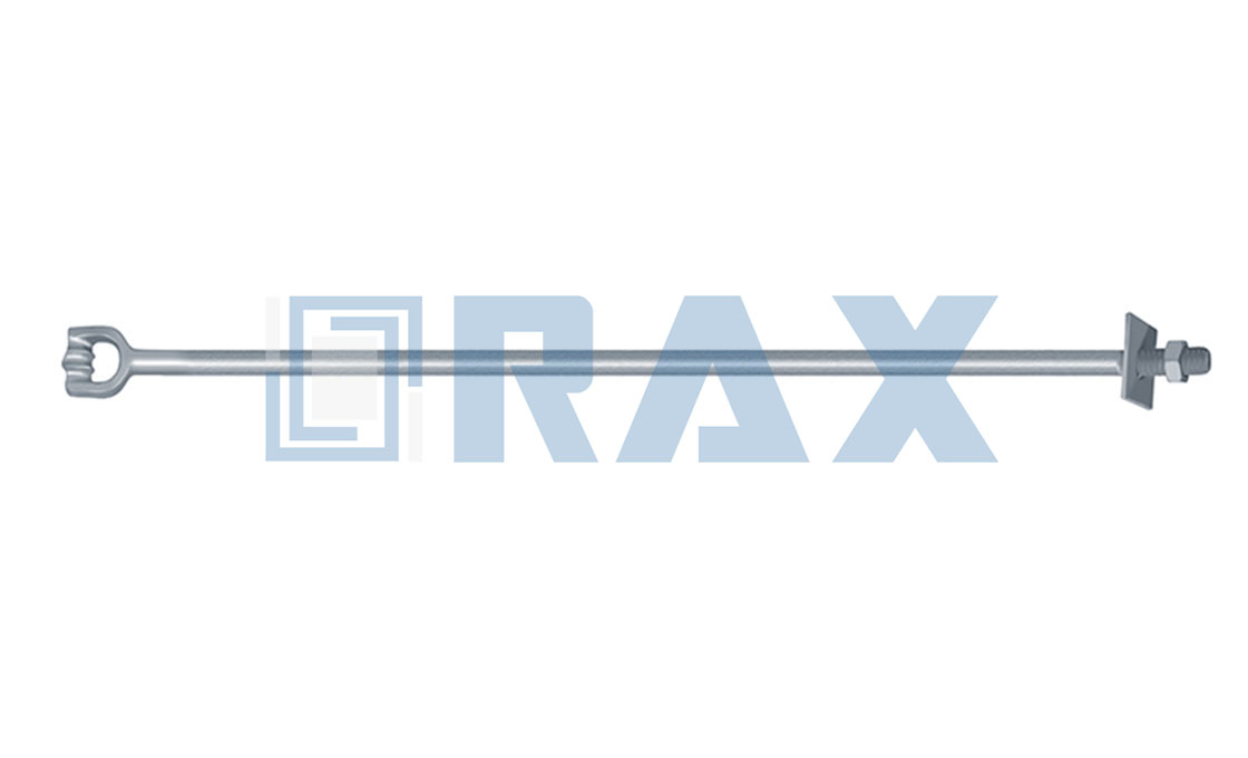
The rod in the photograph looks generic but is not. Eye type, diameter, thread length, and overall length all have to match the anchor below and the hardware above. A rod that is one class weaker than its anchor does not merely underperform. It relocates the system's failure point to ground line, where corrosion and mechanics meet.
How the Load Path Stays Continuous
The system works only while the load path stays continuous and aligned. Conductor tension enters at the pole top and exits through the guy attachment. It travels down the guy strand at a fixed angle, wraps a thimble eye, and runs along the rod below grade. At the bottom, the anchor helix or plate spreads the load into a cone of soil.
Every joint in this chain is a chance to add misalignment, and misalignment converts pure tension into bending. Alignment is a specification, not a habit. One cross-plate anchor spec sheet warns that "installing more than 5° off the guy load alignment significantly reduces strength." Five degrees is a small number with large consequences. The rated capacity assumes the load arrives axially.
Crews that chain-drag the rod sideways to reach the eye are spending capacity they cannot see. In our experience, the cheapest alignment insurance is specifying the assembly in one step. Rod length, eye style, and set angle chosen together mean the field crew never improvises a bend. The way you buy the components decides the way the crew installs them.
Anchor Styles and Where Each Fits
The anchor family decides how the system fights soil. Screw anchors use helix bearing surfaces and install with rotary torque. Expanding anchors, such as cross-plate and expanding-bullet designs, are set in augered holes and then strained open. Driven anchors, from duckbills to manta rays, convert installation impact into holding power. Grouted and rock anchors cover the hard-ground end of the map.
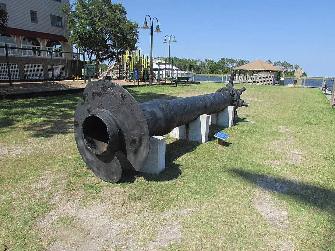
The helix idea is old. The nineteenth-century screw pile in the photograph applies the same principle as a modern helical anchor. Rotation becomes penetration, and the helix plate turns bearing into resistance. What has changed is the soil science around it, and the torque instrumentation that lets a crew verify capacity during installation.
Choosing among styles is a soil-and-load decision, not a brand preference. The site already carries the deep dives: types census for utility poles, a wind-zone selection guide, and a load-versus-soil guide to percussion anchors. The system-level question is narrower. Whichever style you pick, its installed capacity at your lead angle must exceed the guy load with margin.
Soil Class Sets the Holding Capacity
Two identical anchors in two soils can differ in capacity by a factor of five. This is why serious catalogs rate anchors against a soil classification rather than a single number. The classes descend from the Chance soil classification, from Class 1 loose sand to Class 10 sound rock. Classes 4 through 6 cover the clays and mixed soils where most distribution guys land.
Depth is the other half of the promise. Hubbell's holding capacity chart for cross-plate anchors is explicit about the pairing. Hubbell's holding capacity chart for cross-plate anchors pairs capacity with depth. For "Class 3, 4, 5, and 6 soils", it lists the table capacities at "5 vertical feet to the center of the plate". A plate set at three feet is a different, smaller anchor, whatever the catalog says.
The rod must not become the bottleneck while the soil is still winning. MacLean Power's expanding-anchor rod table lists ultimate tensile ratings by diameter. The ladder runs 16,000 lbs at 5/8 inch, 23,000 lbs at 3/4 inch, 36,000 lbs at 1 inch, and 54,000 lbs at 1-1/4 inch. Matching that ladder against the anchor's soil-limited rating is a ten-minute desk exercise.
| Rod diameter | Ultimate tensile strength |
|---|---|
| 5/8 in | 16,000 lbs |
| 3/4 in | 23,000 lbs |
| 1 in | 36,000 lbs |
| 1-1/4 in | 54,000 lbs |
Why Torque Reads the Soil Without Promising
For screw-type anchors, installation torque doubles as a soil measurement. The relationship is documented in Hubbell's Encyclopedia of Anchoring. It finds that "a correlation exists between Installation Torque and Holding Capacity for a given anchor." The anchor torques fast in soft soil and slow in dense soil. The gauge reading is the first honest number a crew gets about the ground it was given.
The word correlation deserves its weight. Torque correlates with capacity for a given anchor geometry; it does not certify it. Torque tables, probe readings, and classification charts all estimate the soil, and the design still needs its safety factor. Helical suppliers note another subtlety: a helix combination's holding capacity may drop 10 to 20 percent against a single-helix rating. Bolt-on extensions are not free capacity.
Picture the foreman who reads 800 ft-lb on the gauge, calls it a verified anchor, and moves on. If the anchor is a multi-helix design in a wet clay, the gauge measured installation effort. It did not measure the cone of soil that will carry a dead-end through an ice storm. Torque is a reading; proof testing is the proof.
The Guy Assembly From Pole to Anchor
Above grade, the anchoring system becomes a guy assembly. Its hardware has to connect three worlds: the wooden or concrete pole, the steel strand, and the anchor rod eye. At the pole, a guy hook, band, or bracket spreads the reaction over the pole face. At the strand, thimbles protect the bend radius while guy grips or clamps make the termination. In between, a strain insulator splits the guy electrically, and a turnbuckle sets the tension.
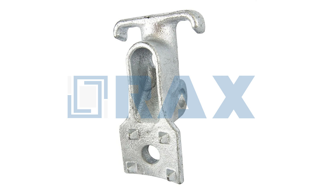
Every one of those parts must carry the same guy load, and each has its own rating ladder. The strand grade sets the ceiling the hardware should follow, not exceed. MacLean's guy strain insulator bulletin describes the component's role plainly. It provides "electrical separation from the pole to the guy wire" while standing in the mechanical path. A fitting that insulates but cannot carry the working load is a safety feature with an expiration date.
The system-level habit is to buy the assembly against the strand specification. When the rod eye, the strand thimble, and the pole hook are sized to one guy design, the assembly tensions evenly. No single fitting becomes the fuse.
Guy Insulator Placement That Follows NESC
Insulator placement is where the anchoring system meets the safety rules. The National Electrical Safety Code requires down guys to be insulated, and placement is not left to preference. The strain insulator must sit high enough that a broken or slackened guy still leaves it at least eight feet above grade. If the wire lets go, the hanging end must stay out of reach of people and equipment.
Ameren's guying standard explains the failure logic behind the height rule. It states that "If the guy wire breaks below the insulator, the insulator will fall below all primary voltage supply conductors and above any secondary" conductors. The insulator is positioned so that an energized section of guy never touches supply equipment, whether the guy is intact or broken.
For the anchoring system this creates a real geometric constraint. The insulator needs a position up the guy that clears the eight-foot rule at the guy's angle. That effectively shortens the adjustable tail near the rod. Ordering a rod with an eye at the right height keeps both the electrical rule and the mechanical angle honest.
Lead Distance and the 45 Degree Rule
Lead distance is the horizontal setback from pole to anchor. It decides how much of the guy's strength actually works against the load. USDA Rural Utilities Service guidance treats 45 degrees as the reference case. Its distribution guying guide notes the angle between guy and pole should be 45 degrees or more, and that 45 degrees occurs when the attachment height equals the lead distance.
That one-to-one rule is the most useful number in the whole system. A 30-foot attachment height wants an anchor about 30 feet out. Shrink the lead and the guy steepens. More of its tension then pushes the pole downward instead of balancing the conductor, and the anchor inherits vertical load it may not be rated for. Extend the lead too far and right-of-way, not mechanics, becomes the limit.
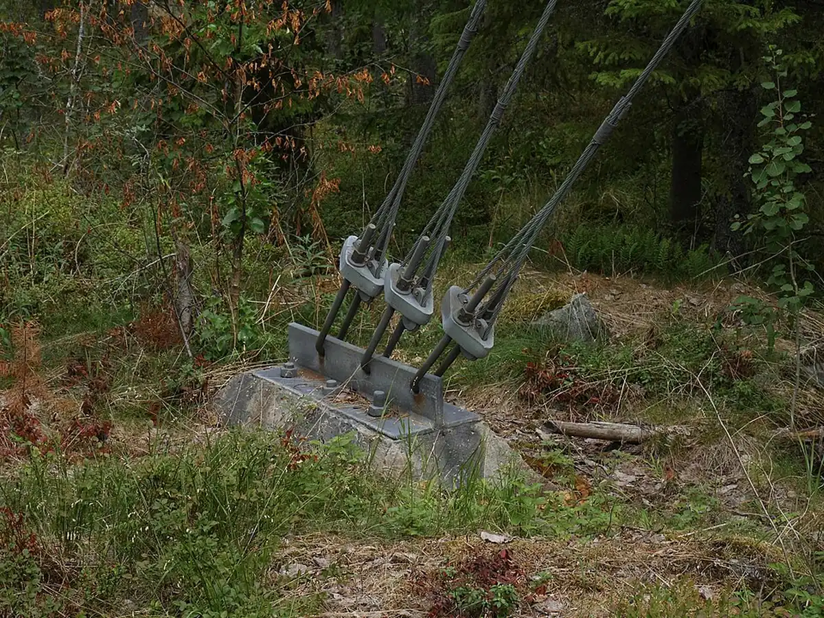
The photograph shows the idea in the field. Anchors sit well back from the structure they brace, with the guys rising at a shallow, working angle. Utility standards and the depth-by-soil guides on this site turn that visual into arithmetic. The arithmetic belongs on the staking sheet before the digger arrives, not after.
A utility pole anchoring system planned this way costs no more at the invoice stage. The same anchor, the same rod, and the same strand simply land where the geometry wants them. What changes is the rework that never happens. No second mobilization to move an anchor, no guy splice invented at the pole, no turnbuckle jammed solid under a misplaced insulator.
When Tangent Poles Need Anchors Too
A tangent pole between two equal spans is already a balanced system. Conductor tensions pull in opposite directions and cancel, which is why straight runs go for long stretches without a guy. Field references on line components note the corollary. Guys stabilize angled or dead-end structures, while tangent poles are rarely guyed because their loads balance out.
The cancellations fail in familiar places. Where the line changes direction, even a few degrees, the resultant force grows and something must absorb it. The same is true where spans lengthen on one side, where a tap leaves the pole, or where elevation drops sharply. Ice and wind events unbalance tangent runs too, which is why some utilities anchor long tangent routes at intervals.
The system lesson is that anchoring need is positional, not universal. Map the route for angle points, grade changes, crossings, and terminations. The number of anchoring systems falls out of the geometry. Every guy placed at a true balance point is capacity spent where the line will never need it.
Dead-Ends Carry Full Tension, Not Half
At a dead-end, the pole stops being a support and becomes a wall. The structural definition used in transmission design is explicit. A dead-end structure is "designed as a termination point for wires, capable of supporting the full tension loads of all wires removed on one face". On distribution poles, that definition lands on the anchoring system. Every foot of tension on the dead side must exit through one guy and one anchor.
Full tension changes the sizing conversation completely. A guy at an angle structure shares its load with the pole's bending stiffness and the next span's balance. A dead-end guy shares nothing. Its anchor, rod, and hardware each see the whole event. This is where rod diameter and soil class earn their margins, and where a proof test of the installed anchor pays for itself.
By the time a dead-end is framed, most of its decisions are locked in the purchase order. The rod class must match the strand's breaking load. The anchor style must suit the soil at that exact structure. The lead must allow a 45-degree geometry. Changing any of them after the auger arrives costs a restock and a schedule slip.
System-Level Failure Modes Beyond the Anchor
Anchors rarely fail alone; they fail as systems. The first family is misalignment failure. Hubbell's post-storm inspection guidance tells crews to install the anchor in line with the guy. Doing so reduces damage to the anchor rod caused by rod bending. A bent rod under repeated load works its metal the way a paperclip works between your fingers until it breaks.
The second family is capacity mismatch. A soil-limited anchor paired with an over-strong rod, or the reverse, puts the failure point where nobody sized it. The third family is degradation at the interfaces. Corrosion attacks the ground line where the rod enters the soil. Thread galling seizes the turnbuckle. Creep, the slow movement of an anchor through soil under sustained load, shows up as a guy that needs retensioning every season.
Each mode has a system-level counter. Alignment counters bending. Matched ratings eliminate the weak link. Hot-dip galvanizing across the whole chain counters the ground line. An installed proof load counters creep before it counters you. A storm inspection that checks only visible hardware misses the modes that start underground, so walk the lead and look for disturbed soil.
There is a fourth family that belongs to procurement rather than the field: documentation mismatch. An anchor rated on old data, a rod from a different revision, or hardware certified to a superseded standard weakens the system on paper. That happens long before any load tests it. Keep the certificates with the staking sheet, and the system keeps its paper trail as intact as its load path.
What the Staking Sheet Must Fix Early
Every decision in this guide has a home on the staking sheet, and the home matters more than the sheet's format. A utility pole anchoring system fails most often in the handoff between design and field, where a note like "guy and anchor, typical" replaces actual numbers. A staking note that fixes the anchor location, the lead, and the rod eye height leaves the crew only execution choices, which are the choices crews are equipped to make.
Three numbers deserve to be written, not implied. The first is the soil class, because it sizes the anchor and the depth together. The second is the lead distance in feet, because it sets the guy angle that every hardware rating assumes. The third is the working load at the attachment, in pounds, which lets the supplier check the rod, the anchor, and the strand against one figure instead of three guesses.
When those three numbers travel with the purchase order, the anchoring system arrives as a kit rather than a pile. The supplier can pre-match eye styles to hardware and confirm thread compatibility before anything ships. The crew can set the anchor to the staked point without improvising geometry. Nothing in that sequence is advanced engineering; it is discipline applied where it is cheapest, on paper.
A Checklist Before the First Dig
Everything above compresses into eight questions, best answered at the desk before equipment rolls:
- Structure type and its load case: tangent reinforcement, angle point, or full-tension dead-end?
- Soil class at the anchor location, from the probe or the jurisdiction's soil maps.
- Guy attachment height, which fixes the ideal lead distance at one-to-one.
- Anchor style and depth matched to that soil class, with capacity plus safety factor.
- Rod diameter and eye style carrying the guy load with margin, thread-compatible hardware.
- Strand size and grade, with grips, thimbles, and turnbuckles sized to the strand.
- Guy strain insulator position clearing the eight-foot rule on both intact and broken guys.
- Proof load plan for the installed anchor, and a retensioning check scheduled after settling.
A staking sheet that answers these eight lines produces one purchase order instead of three. It produces one assembly instead of three guesses. The guides to anchor depth by soil type and to wind-zone selection plug directly into lines two and four.
Why the System View Outlasts Components
RaxPower has manufactured pole line and overhead line hardware since 2003. The anchoring inquiries that end best are the ones that arrive as systems. When the anchor, rod, and guy hardware are chosen against one soil class, one lead geometry, and one strand specification, the installed assembly behaves like the sum the catalog promised.
Treat every guy as a chain of five links: soil, anchor, rod, hardware, and geometry. Audit the weakest link before the dig, not after the storm. That is the entire discipline of the utility pole anchoring system, compressed into one walk around the pole.
None of it requires exotic hardware. It requires that the utility pole anchoring system be bought, staked, installed, and inspected as a single thing. Lines that do this spend their maintenance budget extending life, not discovering which link quietly gave up first.
That is the quiet argument for treating the utility pole anchoring system as one catalog conversation. The components are mature, the standards are stable, and the geometry is arithmetic. The only variable a buyer fully controls is whether the links were chosen together.
Frequently Asked Questions
What makes a utility pole anchoring system fail first?
Usually the mismatch, not the component. A soil-limited anchor behind an over-strong rod, a rod bent off the guy axis, or an unproofed anchor creeping in soft soil until the guy goes slack.
How far from the pole should the anchor be set?
Set the lead distance roughly equal to the guy attachment height. That one-to-one setback produces the 45-degree guy angle treated as the reference case in RUS distribution guidance.
Why must a guy strain insulator sit high on the guy?
So a broken or slack guy still holds the insulator at least eight feet above grade, and the falling energized end clears primary conductors on its way down.
Does installation torque guarantee anchor holding capacity?
No. Torque correlates with holding capacity for a given anchor and soil, so it is a strong field reading, but rated capacity still requires soil data and a safety factor.
Which anchoring components should be ordered together?
Anchor, anchor rod, and guy hardware as one assembly: matched to one soil class, one strand size, and one lead geometry so no link becomes the fuse.