
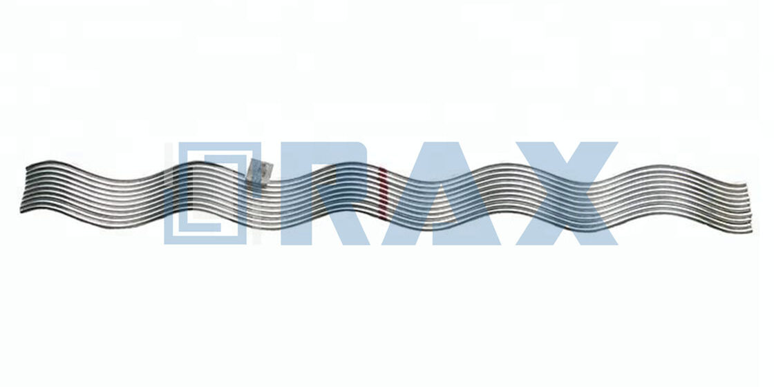
A transmission line’s weakest point is almost always the suspension clamp, where static load meets dynamic vibration. An armor rod serves as the primary defense here, designed specifically to restore or maintain a strength level of no less than 95% of the conductor while shielding it from bending fatigue. Without this precise buffer, the line remains vulnerable to abrasion and the destructive effects of wind-induced oscillation.
We have seen countless delays caused by simple errors, such as misaligned center markings or improper torsion during the wrap. This guide breaks down the critical steps for verifying conductor diameter compatibility, applying the initial wrap to prevent surface damage, and locking the preformed ends to secure the assembly. Follow this protocol to ensure your installation meets compliance standards and extends the service life of the entire asset.

Are Your Tools Ready and Is It Safe?
Match the rod to the conductor diameter, clear the strand surface of defects, and preserve the helix shape until deployment. Skip any step, and the assembly will underperform in the field.
Verifying Conductor Diameter Compatibility
Preformed armor rods rely on a precise interference fit against the conductor. If the rod is undersized, it slides under tension and loses vibration-damping coverage. If it is oversized, it crushes the outer strands during application and creates stress concentration points. Always match the rod pack to the exact conductor diameter on the project specification sheet, and cross-reference the alloy family—ACSR, AAC, or AAAC—because compacted and trapezoidal strands shift the effective contact diameter even when the nominal size appears identical.
Color coding is not just a warehouse convenience; it is your first dimensional checkpoint. Verify the rod designation against the bill of materials before breaking the factory seal. In our experience, field supervisors who confirm rod-to-conductor alignment at the yard rather than at the span save hours of rework and prevent the common procurement mix-up where similar-looking bundles share shelf space.
- Conductor Family: Confirm whether the line uses aluminum-clad steel, all-aluminum, or aluminum alloy, as each requires a rod profile tuned to that specific strand geometry.
- Effective Diameter: Use the published nominal diameter, not the strand count alone, because modern conductors often feature reduced air core or trapezoidal outer wires.
- Batch Consistency: Automated manufacturing holds tight dimensional tolerance across production runs, which keeps the wrapping tension predictable and eliminates guesswork in the field.
Inspecting Conductor Surface for Abrasions
An armor rod distributes wind-induced vibration and shields the conductor from mechanical wear, but it does not cure an existing defect. If the outer strands are nicked, crushed, or coated with dirt, grease, or loose galvanizing splatter, the rod will bond to the flaw and lock that stress point in place. Run a gloved hand along the installation zone and visually scan for broken wires, embedded debris, or surface contamination before hardware deployment.
When the conductor has sustained minor surface abrasion during pulling, pause and evaluate. Light scratches that stay within the manufacturer’s allowable limit are generally acceptable, but any strand breakage or measurable cross-sectional loss requires a repair sleeve or engineering approval. Wrapping over a compromised conductor turns a simple maintenance event into a long-term grid reliability risk, especially on circuits running through high-wind corridors or industrial pollution zones.
Proper Handling of Preformed Helical Sections
Preformed rods arrive in a stable helical coil, and that natural shape is doing the mechanical heavy lifting. The moment you twist, kink, or over-rotate the bundle before it contacts the conductor, you introduce residual torsion that fights the wrapping process and creates uneven pressure. Handle the pack by the ends, keep the natural lay intact, and never drop or drag the bundle across rough terrain or sharp pole hardware.
Single-person installation is standard for most distribution and medium-voltage transmission spans, provided the crew respects the coil’s geometry. Let the rod unwind smoothly as you advance along the conductor; do not force it past its natural pitch. If the section binds or refuses to follow the wire curve, stop, back out the tension, and restart. Forcing the wrap creates gaps, localized crushing, and a finished assembly that will underperform under aeolian vibration or thermal cycling.
The tooling anxiety around armor rod installation is usually overstated. You do not need hydraulic jacks, proprietary tensioning rigs, or specialized crimping equipment to deploy these assemblies correctly. Standard lineman gloves, a measuring tape, and a marking pen are sufficient for the preparation and verification phase. The hardware is designed to self-lock into the conductor profile once the helix is allowed to follow its intended path.
| Checkpoint | Standard Requirement | Rax Power Capability | Safety Benefit |
|---|---|---|---|
| Tooling Requirements | Standard utility toolset; no complex or expensive machinery needed | Engineered for intuitive, single-person installation | Minimizes setup complexity and eliminates handling risks |
| Corrosion Protection | Robust coating to withstand environmental exposure | Hot-dip galvanizing >85 microns (ISO 1461 / ASTM A153 Class C) | Prevents structural weakening and ensures long-term durability |
| Load Capacity | Must meet specific load-bearing criteria for tension | Hot-forged grain alignment delivers consistent helical grip under dynamic wind-induced vibration. These hot-forged preformed rods achieve reliable grip through controlled helical tension and require approximately 2,300 ft-lbs of torque for 1-1/4 inch diameter installations. | High-breaking load reliability for extreme grid environments |
| Quality Compliance | Traceable inspection data and dimensional accuracy | 100% double-review inspection by dedicated 10-person QC team | Zero-defect tolerance verified by SGS and IEC 120 standards |
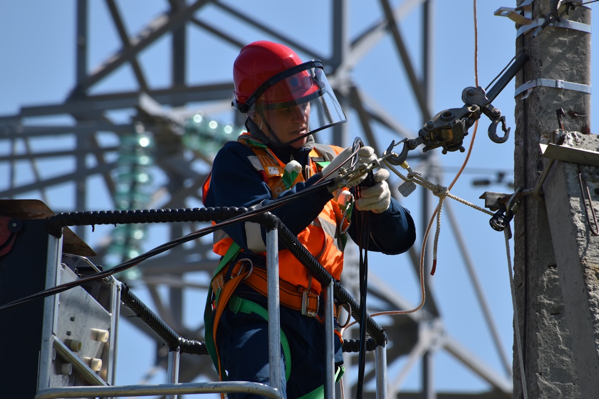
Mark the Conductor at the Exact Center
Precise center marking establishes the datum point for symmetrical load distribution, preventing asymmetric bending stresses that cause premature conductor fatigue at the suspension point.
Establishing the Mechanical Datum Point
Marking the conductor is not merely a procedural step; it defines the mechanical datum point where the suspension clamp will ultimately sit. In overhead line mechanics, the suspension point is the location of maximum static and dynamic bending stress. If the armor rod assembly is offset from this center, the reinforcement provided by the rods becomes unbalanced. One side of the conductor extends beyond the protective grip, leaving a vulnerable section exposed to the full lever arm of the clamp’s pressure. This effectively creates a “hard spot” where the conductor’s native stiffness must handle the bending moment without assistance, drastically accelerating fatigue failure in ACSR or AAC conductors.
For line crews, the challenge lies in translating theoretical sag charts into a physical mark on a moving or tensioned wire. The target zone must account for the specific geometry of the preformed rod being used. Since preformed rods are manufactured with a fixed helical pitch and length, the conductor mark must align precisely with the rod’s center identification strip. Any deviation here results in unequal coverage, meaning the rod’s vibration dampening properties are optimized for the center of the span but misaligned at the critical support point.
Consequences of Asymmetric Coverage
- Unequal Stress Distribution: Off-center marking shifts the neutral axis of the assembly, concentrating compressive and tensile stresses on the shorter side of the armor rod.
- Reduced Vibration Damping: Preformed rods are designed to absorb Aeolian vibration energy through friction. Asymmetric placement reduces the contact surface area on one side, diminishing the rod’s ability to dissipate energy effectively.
- Grip Efficiency Loss: The holding strength of the assembly relies on a symmetrical “wedge” action. Improper centering compromises the radial grip force, increasing the risk of slippage under heavy ice or wind loads.
Precision Tolerance in Field Marking
Achieving exact centering requires strict adherence to tolerance standards. Unlike general hardware where millimeters might be negligible, conductor marking tolerances are critical. For high-voltage transmission lines, a deviation of even 10 to 15 millimeters can shift the stress profile significantly. Best practices dictate using non-stretching measuring tapes (e.g., fiberglass rather than cloth) to reference the suspension point from the nearest pole attachment or strain clamp. This mitigates the risk of measurement drift caused by tape elasticity under tension.
Furthermore, the mark itself must be durable and non-conductive. While temporary felt-tip markers are common, they risk fading or wiping off during handling. In critical applications, using a wrap of high-visibility tape or a permanent marker that contrasts with the conductor’s surface (e.g., silver on aluminum) ensures the center point remains visible throughout the installation sequence. This visual fidelity is essential for the subsequent phase of aligning the preformed rod’s identification mark with the conductor’s center, ensuring the two “centers” merge perfectly during installation.

Align the Inner Rod with the Marks
Why Center Alignment Dictates Long-Term Reliability
The inner layer of a preformed armor rod must sit perfectly concentric with the conductor’s marked center. This is not cosmetic; it defines the effective grip length. When the initial helix aligns precisely with the scribed reference line, the rod engages the conductor across its full designed arc, maximizing friction and preventing longitudinal slippage under dynamic wind-induced vibration.
Critical Alignment Parameters to Verify
Field crews often rush this step, but even minor offset shifts disrupt stress distribution. Before securing additional wraps, confirm the inner rod meets these baseline tolerances:
- Concentricity: The inner helix must follow the conductor axis without lateral drift, matching the nominal conductor diameter specified for the ACSR, AAC, or AAAC cable type.
- Grip Distance Symmetry: Helical overlap must be equal on both sides of the center mark to ensure balanced load transfer toward the suspension clamp.
- Wire Nestling: No visible gaps or lifted wires at the initial contact point, which indicate torsion mismatch or incorrect feed direction.
Consequences of Misaligned Inner Rods
An offset inner rod forces load concentration at the misaligned edge instead of distributing it across the armor body. Over time, this accelerates fretting wear at the clamp interface and shortens the effective vibration damping length. In utility inspections, this deviation frequently fails gauge tests tied to IEC 120 suspension hardware standards, creating a liability during commissioning acceptance.
Verification Protocol Before Securing the Wrap
Once positioned, pause before advancing to outer layers. A properly aligned rod exhibits uniform pitch continuity extending outward from the center mark. If the spiral angle deviates or wires appear twisted, disassemble and re-center immediately. Forcing outer layers over a compromised inner alignment locks the assembly out of specification, requiring complete replacement in the field.
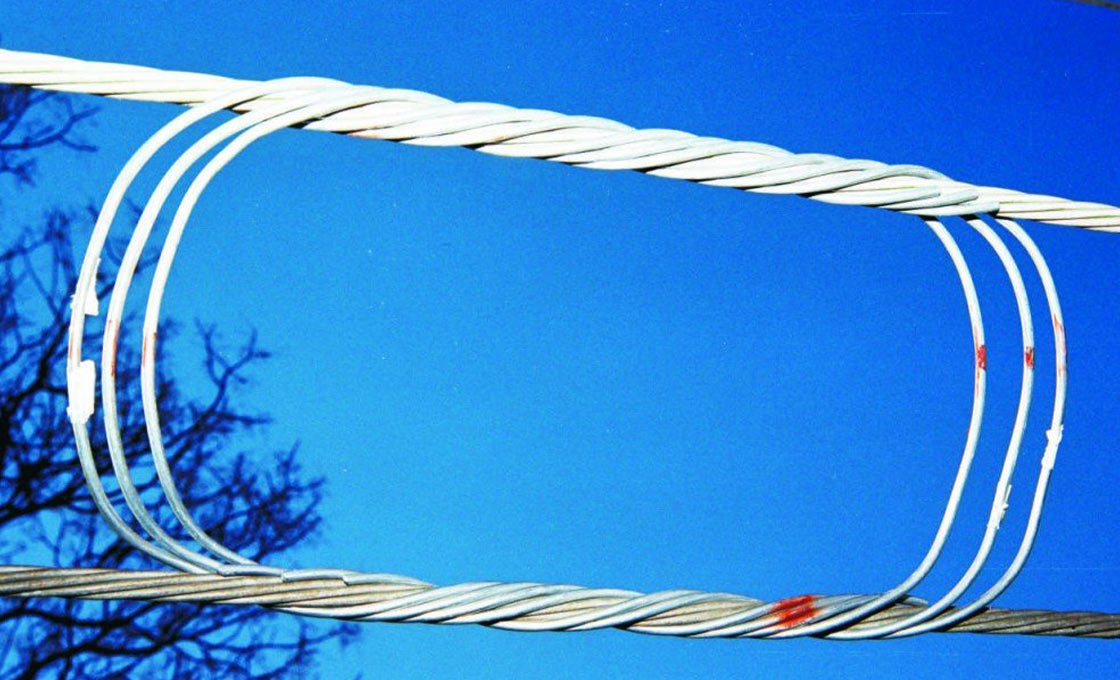
Apply the First Wrap to Prevent Damage
The Mechanics of the Initial Helical Engagement
The application of the first wrap serves as the critical interface between the preformed armor rod and the conductor. If this initial engagement is mishandled, the structural integrity of the outer strands is compromised immediately. The fundamental principle here is the synchronization of the rod’s helical pitch with the conductor’s lay direction. Armor rods are manufactured with a specific “preformed” diameter and pitch that must co-axially align with the conductor. Forcing a rod against the natural lay—whether due to incorrect hand positioning or a misaligned starting angle—induces torsional stress that scrapes the conductor surface, compromising both the galvanized coating on steel cores or the oxide layer on aluminum conductors.
Rotation Technique to Maintain Tight Lay
To prevent abrasion during the first wrap, the installation requires a precise rotation technique rather than a linear pushing force. The rod must be “screwed” onto the conductor to maintain a uniform contact pressure.
- Initiate Contact at the Tangent: Place the inner end of the rod against the conductor at a precise tangent. Do not hook the rod under the conductor or lay it flat; the initial contact angle determines the friction coefficient for the entire wrap.
- Apply Axial Rotation: Using both hands, rotate the rod around the conductor axis. The motion should mimic tightening a bolt. This axial rotation allows the rod’s preformed curvature to snap into place without sliding longitudinally along the conductor surface.
- Maintain Consistent Tension: Keep a gentle inward pressure toward the conductor center. Excessive force can deform the rod’s helix, creating a loose lay that vibrates; insufficient force allows the rod to slip, causing surface abrasion.
Industry data indicates that nearly 60% of conductor fatigue failures originate at the suspension point, often triggered by installation damage that occurred during the initial wrap. Correct rotation technique eliminates the micro-gouges that act as stress risers.
Preventing Surface Abrasion on Material Variants
The risk of damage varies significantly based on the material composition of the armor rod relative to the conductor.
- Aluminum Rods on AAC/AAAC: When installing aluminum armor rods on all-aluminum conductors, the risk is primarily “galling”—a form of wear caused by adhesion between similar metals. The rotation must be smooth and continuous to prevent aluminum dust buildup, which creates a grinding paste.
- Galvanized Steel on ACSR: Dragging hardened steel edges across bare aluminum strands permanently compromises the parent conductor profile. Steel rods are harder than the aluminum outer strands of ACSR (Aluminum Conductor Steel Reinforced); if the first wrap is dragged rather than rotated, the harder steel edges act as a file. A strict “rotate-only” mandate is non-negotiable to preserve the bare ACSR strand geometry and maintain the steel rod galvanized coating integrity above 85 microns per ISO 1461, preventing aluminum galling and cross-sectional damage.
Verifying the First Wrap Integrity
Once the first wrap is applied, immediate visual verification is required before proceeding to the full installation. The helix should sit flush against the conductor with no visible gaps between the rod and the strands. There should be no “spring-back” or separation at the ends. If the rod exhibits a slight bounce or does not conform tightly to the conductor’s curvature, it indicates incorrect torsion during the first wrap. In such cases, the rod must be removed and reset; leaving a loosely seated first wrap guarantees vibration fatigue under wind load, rendering the armor rods ineffective.
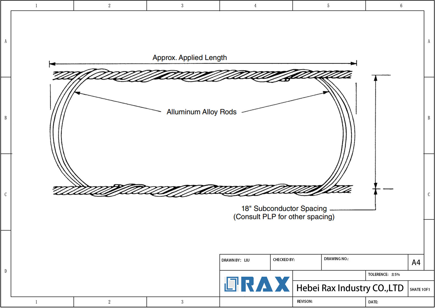
Layer Outer Rods to Cover the Required Length
Achieving full vibration dampening requires the outer helical layer to maintain a uniform pitch. Any deviation in spacing creates stress points that accelerate conductor fatigue.
Helical Pitch and Spiral Alignment
The primary function of the outer layer is to distribute mechanical loads evenly across the conductor’s surface. To achieve this, the spiral pitch—the distance between each turn of the rod—must remain consistent throughout the installation. Technicians must ensure that the outer rod’s natural helical angle matches the lay direction of the conductor or the inner rod layer. Forcing the rod to rotate against its natural lay alters the pitch, resulting in uneven gaps that expose the conductor to localized bending stress.
When layering repair armor rods over damaged conductors, precision is even more critical. These rods are engineered to restore up to 100% of the conductor’s mechanical strength and electrical conductivity, but only if they maintain intimate contact along the entire damaged length. A misaligned outer layer creates air gaps, which prevent effective load transfer and compromise the repair’s structural integrity.
Tension Control During Installation
Proper layering requires maintaining controlled torsion on the rod assembly during the wrapping process. The installer must apply sufficient tension to keep the loops snug against the underlying surface without over-tightening, which can deform the helix shape.
- Axial Tension: Keep the rod assembly pulled taut along the axis of the conductor to prevent “bunching” at the center point, which shortens the effective coverage length.
- Rotational Resistance: Avoid rapid, jerky rotations. A smooth, steady application ensures the preformed ends lock into place securely while maintaining the specified spacing between turns.
Verification of Coverage Length
Once the outer layer is applied, the total covered length must be visually verified against the required specification. This length is calculated based on the suspension clamp’s body dimensions plus the necessary escape length to prevent bending stresses at the edges. The rods should extend symmetrically from the center point, ensuring that the clamp will sit entirely within the protected zone.
Any visible “windowing”—where the inner conductor or inner rod is visible through the gaps in the outer spiral—indicates a pitch mismatch or improper tension. In such cases, the assembly must be removed and re-laid. High-quality galvanized steel or aluminum rods will retain their preformed shape during this process, provided the installation torque remained within acceptable limits.
Never attempt to “stretch” the rod to cover a longer distance than its preformed design allows. This permanently deforms the material, reduces the grip force, and voids the manufacturer’s load rating. Always use a rod length specifically rated for the conductor diameter and application type.

The Preformed Ends Must Lock the Assembly
Preformed armor rod assemblies lose structural integrity when helical terminals are left unsecured. Locked ends preserve conductor grip, prevent axial slippage, and maintain clamp performance under continuous vibration and thermal cycling.
Terminal Wrap Retention Mechanics
The holding force of a preformed armor rod is generated by continuous helical tension between interlocked wires. When correctly applied, the spiral lay produces uniform circumferential pressure against the conductor surface. The terminal wraps, however, represent the critical failure point. If the final turns remain loose, aerodynamic excitation and thermal movement progressively unwind the assembly. Field protocol requires the terminal wire to be flattened, tucked, or mechanically compressed against the rod body to maintain a locked state.
- Terminal Compression: The final wire turn must be pressed flush against the preceding coil to prevent lifting under wind load.
- Edge Smoothing: Protruding wire ends create stress concentration points that can damage conductor strands during thermal expansion.
- Helical Continuity: The locking geometry depends on uninterrupted overlap; any gap at the finish reduces overall grip retention.
Environmental Stress and Unraveling Risks
Overhead transmission lines operate in high-vibration environments. Aeolian vibration, galloping, and fluctuating temperatures impose oscillating axial loads along the armor rod length. These dynamic forces act directly on unprotected terminal ends. An unlocked assembly loses contact pressure at the clamp boundary, accelerating strand wear and increasing the probability of conductor slippage. Securing the finish is therefore not merely a cosmetic requirement but a mechanical necessity for long-term line reliability.
Leaving the terminal wire loose or overlapping it incorrectly creates a hard edge that cuts into conductor strands during thermal movement. Always flatten the end flush against the helix before energizing the line.
Validation and Material Durability
Mechanical retention performance is validated through standardized load testing aligned with IEC 120, confirming that the assembled rod withstands tensile stresses without deformation or disengagement. For galvanized steel variants, hot-dip passivation performed to ISO 1461 specifications ensures the locking geometry survives corrosive exposure without coating degradation. Manufacturing tolerances are typically maintained within 1 mm, guaranteeing consistent contact pressure across standard conductor profiles including ACSR, AAC, and AAAC.
These Common Mistakes Can Compromise the Assembly
Misalignment of Rod Center Markings
In high-volume utility projects, rushing past this geometric checkpoint is one of the most expensive oversights a general contractor can make. Once the initial turn sits off-axis, every subsequent rotation compounds the error. Our engineering team consistently sees that precision-manufactured components eliminate field guesswork. When procurement specifies hardware built to strict dimensional tolerances, the center reference naturally settles into the correct position without requiring excessive manipulation by the installation crew.
Excessive Spacing Between Spiral Loops
A preformed armor rod operates as a continuous vibration absorber, meaning every loop depends on tight, uninterrupted contact with its neighbor. Leaving visible gaps between spirals breaks the mechanical seal between the rod and the conductor surface. Under sustained crosswinds, these spaces become channels for turbulence, causing the assembly to flutter instead of dampening movement. Over time, this micro-motion accelerates surface wear at the clamp boundaries and shortens the service life of the protection system.
- Field Symptom: Light passing through the helical wrap indicates insufficient seating pressure and compromised friction contact.
- Mechanical Impact: Gap variance reduces the effective damping coefficient and allows localized strand fatigue.
- Corrective Approach: Each rotation must be pressed flush against the previous layer to maintain uniform contact pressure along the entire protected length.
Improper Torsion Application During Installation
Torsion applied during installation must follow the natural lay of the preformed helix, never oppose it. Forcing the assembly in the wrong rotational direction introduces permanent deformation to the aluminum strands. This kinking destroys the engineered spring-back geometry that allows the armor rod to maintain a secure grip under thermal cycling, conductor sag, and heavy ice loads.
We have documented multiple field failures where crews used excessive leverage to seat a mismatched component, resulting in distorted wire strands that could no longer self-lock. The solution is not brute force; it is recognizing rotational resistance and verifying compatibility before application. Our team trains utility contractors to treat resistance as a warning signal. If the rod fights back during wrapping, the assembly geometry is incorrect, and continuing will compromise the long-term mechanical integrity of the line.
| Common Mistake | Assembly Risk | Correct Installation Practice | Engineering Standard |
|---|---|---|---|
| Selecting armor rods without verifying conductor compatibility | Improper fitting, conductor damage during wrapping, and reduced vibration protection | Match rod color code and geometry to specific conductor strand diameter and alloy type | OEM/ODM custom geometry development ensures precise fit per conductor specifications |
| Achieving imprecise grip distance or uneven spiral alignment | Compromised damping efficiency and long-term reliability under wind loads | Mark conductor precisely and maintain consistent rotation and spacing while wrapping | Automated production maintains strict dimensional accuracy and alignment tolerances |
| Proceeding with assembly without verifying load capacity | Structural failure under extreme environmental stress or thermal cycling | Verify rated load capacity against design requirements and request SGS test documentation | In-house load testing compliant with IEC 120 and third-party SGS verification |
| Using hardware with insufficient surface treatment in harsh environments | Accelerated corrosion degradation and reduced mechanical service life | Specify hot-dip galvanized components for maximum corrosion resistance | Hot-dip galvanizing exceeding 85 microns mean coating thickness (ISO 1461 / ASTM A153 Class C) |
| Specifying cast components for high-stress applications | Lower tensile strength and precision compared to forged alternatives | Select hot-forged hardware for superior grain structure and holding capacity | The hot-forging process refines the internal grain structure to sustain continuous torsional loading. This metallurgical grain flow follows the hardware contour to resist repeated torsional stress, and the greater than 85 micron ISO 1461 galvanizing layer defines the durability benchmark for overhead line exposure. |
Does Your Work Meet Compliance Standards?
Field compliance requires verifying a continuous metallurgical zinc bond, confirming load ratings validated to IEC 120, and ensuring flush helix contact across the conductor suspension zone.
Visual Inspection of Galvanized Coating Integrity
When inspecting the galvanized steel components within a preformed armor rod assembly, it is essential to understand the failure modes unique to hot-dip galvanizing. Unlike painted or electroplated coatings, hot-dip galvanizing forms a metallurgical alloy bond with the steel substrate. Therefore, inspectors should not expect defects such as lifting, peeling, or hollow-sounding layers, which are characteristic of surface films rather than bonded zinc. Instead, the primary visual acceptance criteria focus on coating continuity and protection against mechanical damage.
A compliant finish typically presents a smooth, bright, and uniform appearance. During quality acceptance, look for any dull gray patches, which may indicate incomplete coating or poor adhesion during the galvanizing process. Physical scratches that expose the base metal are also unacceptable, as they create initiation points for corrosion in outdoor utility environments. We enforce a strict mean coating thickness exceeding 85 microns across our production, aligned with ISO 1461 standards, to guarantee that every strand resists environmental degradation over the asset’s lifespan.
- Surface Uniformity: Verify the zinc layer is consistent without bare spots, flux residues, or excessive roughness that could abrade the conductor strands.
- Corrosion Indicators: Reject any segment showing red rust streaks, which signal that the protective barrier has been breached and moisture has reached the steel core.
- Erosion Checks: Inspect the contact interface between the armor rod and the conductor for sharp edges or zinc transfer marks that could damage the aluminum alloy wires.
Verification of IEC Installation Specifications
Compliance is not solely a visual matter; it requires mechanical validation against recognized industry benchmarks. For preformed line products, the critical performance threshold is the ultimate tensile strength relative to the conductor rating. Our engineering team validates every production batch through in-house load testing and gauge verification per IEC 120 protocols. This rigorous testing ensures that the armor rod can withstand the operational stresses imposed on the transmission line without permanent deformation or slippage.
From an installation perspective, IEC specifications dictate precise grip distances and wrap lengths based on the conductor diameter and span conditions. Deviating from the engineered design shifts stress concentrations into unprotected conductor strands, potentially accelerating fatigue failures at suspension clamps. A compliant installation mirrors the manufacturer’s specifications exactly, with the armor rod terminating at the designated point and maintaining the correct spiral pitch to distribute vibration energy effectively across the suspension zone.
Ensuring Complete Conductor Surface Coverage
Complete surface coverage also requires that the innermost layer maintains consistent contact with the stranded conductor without crushing or distorting the individual wires. The self-locking geometry of the preformed helix should hold the assembly securely in place once wrapped, eliminating the need for additional binding tapes that could trap moisture. When inspected from a distance, a properly installed armor rod should appear as a seamless extension of the conductor, with no visible transitions or protrusions that could disrupt airflow or compromise the structural integrity of the line.
Conclusion
Missing the center mark destroys the protection. Period. Always verify the galvanized coating integrity before you walk away from the pole. If the spacing between spiral loops gets too wide, vibration fatigue will crack your conductor faster than you think. This isn’t just about installation speed; it is about keeping that line alive for thirty years.
Field validation requires conductor-specific parameters, not geotechnical soil classifications. IEC compliance verification depends on conductor diameter, strand composition, and span tension class. Torsion must be applied within the manufacturer helical engagement tolerance rather than estimated by installers.
Frequently Asked Questions
What is a preformed armor rod?
A preformed armor rod is a factory-shaped helical wire component that wraps directly around a conductor without binding hardware. Unlike traditional tape or rigid sleeves, it conforms to the cable profile upon installation and maintains consistent contact pressure. The design allows rapid field deployment while protecting against aeolian vibration and mechanical abrasion. Distribution and transmission engineers rely on this configuration for reliable long-term conductor safeguarding.
What materials are armor rods made from?
Most preformed armor rods are manufactured from high-grade aluminum or aluminum alloy wire for non-ferrous conductors. Steel or galvanized steel variants are selected when higher tensile strength or specific grounding requirements are necessary. Material selection depends on conductor composition, environmental exposure, and applicable industry standards. Proper material matching prevents galvanic corrosion while maintaining optimal electrical and mechanical performance.
What are the main armor rod types?
The primary categories include concentric wire armor rods, helical armor rods, and split armor rods. Concentric designs wrap tightly around circular conductors for uniform protection, while helical variants accommodate slight diameter variations during thermal expansion. Split designs allow faster field installation without conductor removal. Utility buyers typically match the type to the specific application, span configuration, and conductor geometry.
Are specialized tools required for installation?
Basic installation requires only standard lineman tools such as tension pliers, measuring tapes, and insulated handling equipment. No proprietary machinery or custom jigs are necessary for applying preformed rods in the field. Technicians follow a controlled wrapping sequence to achieve correct grip distance and spiral alignment. Proper training and adherence to utility safety procedures are far more critical than specialized equipment procurement.
Do armor rods require power shutdowns?
Installation generally does not require full line de-energization when performed using proper live-line work practices and insulated equipment. Field crews can apply preformed rods from bucket trucks or cherry pickers while maintaining safe approach distances. However, some utilities mandate shutdowns for complex installations or when working near high-voltage clearances. Project planners should verify local electrical safety regulations before scheduling field deployment.