
Picture the weakest point on an aerial fiber route. It is rarely the glass inside the cable. It is the handful of contact points where ADSS cable hardware grips, suspends, and anchors the cable between poles. Every safety feature in that hardware exists to keep those contact points from becoming failure points.
Since 2003, RaxPower has built pole line and overhead line hardware in Hebei, China, and its 170+ person company workforce today supplies a dedicated fiber optic fitting line. Our product notes read like field notes: grip mechanics, jacket chemistry, and galvanizing quality decide whether a fitting protects a 25-year cable or quietly damages it. The mechanisms below are the ones a line designer meets first.
Why Cable Protection Decides ADSS Line Reliability
ADSS cable carries no metal. Aramid yarn takes the tension, the jacket takes the weather, and the optical fibers take none of the strain by design. That makes the cable light, safe near energized conductors, and completely dependent on its fittings for mechanical survival.
A fitting that crushes, chafes, or over-bends the jacket attacks the aramid underneath. Damage hides inside the cable body, so the first visible symptom is usually an OTDR trace drifting out of specification months after energization. Good ADSS cable hardware prevents the damage instead of revealing it.
In hardware terms, a safety feature is any design choice that removes a failure mode before it can start. Five families cover the job. Grip spreads tension, cushions stop crush, dampers eat vibration energy, and dielectric construction removes electrical hazards. Geometry respects the cable’s bend and diameter limits. Each section below takes one family and explains the failure it prevents.
Stress-Free Grip: How Helical Rods Spread Load
Preformed rod grips wrap the cable in layered helical coils, usually aluminum alloy or aluminum-clad steel wire on ADSS lines. The wrap behaves like a spring bandage. Tension in the cable tightens the coils, so grip force grows with load instead of staying fixed at two bolt points.
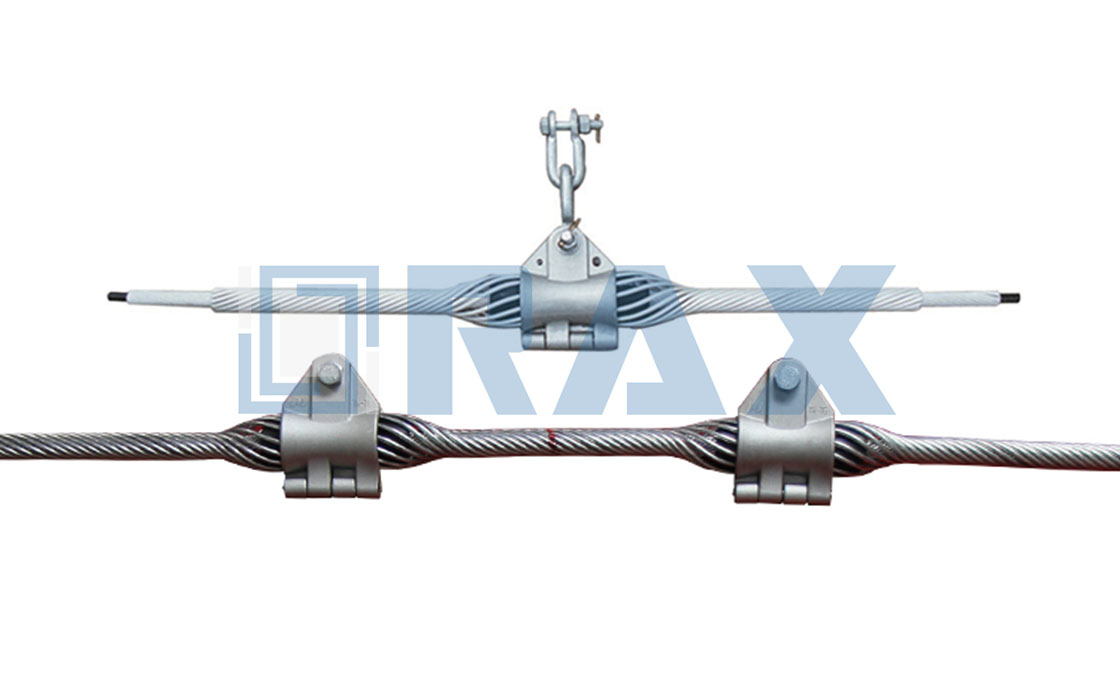
Manufacturers rate these dead-end sets above 95% of the cable’s rated tensile strength, with no stress concentration at any single strand. Tension spreads along the entire lay length, as if the cable were held by many small hands rather than one clenched fist. The same logic drives armor rods at suspension points, which spread load over a larger area and shield the jacket from abrasion. Nothing pinches. Nothing concentrates.
Cushioned Suspension Points Prevent Crush Damage
At every support pole, the cable’s weight and slope tension meet a curved shell. Suspension clamps answer with a neoprene or elastomer insert that cradles the jacket. The insert acts as a shock absorber, spreading compressive load so the shell never bites into the cable.
The insert also permits micro-movement under wind and temperature swing, as if the cable sat in a soft hinge rather than a rigid jaw. Because the contact surface is non-metallic, the cable stays electrically isolated from the pole and its hardware. That matters on shared power routes, where a conductive clamp could invite tracking or corona at the support. For a closer look at one such assembly, see this ADSS suspension clamp.
Keeping Aeolian Vibration From Fatiguing the Jacket
Steady laminar wind sheds vortices off a cable and sets it humming, typically between 3 and 150 Hz with barely visible amplitude. When the wind holds in that 1-7 m/s band for hours, each cycle bends the cable a little at the same spot. All of that bending concentrates within a few centimeters of the clamp lip.
Over twenty years, that adds up to billions of small flexes, enough to abrade a jacket and fret the aramid inside. Vibration dampers absorb the energy before it accumulates. Spiral rod dampers wrap a meter or so of cable and damp broadly with forgiving placement, while tuned Stockbridge dampers target specific frequencies with precise positioning. A practical starting rule places two dampers, one per end, on spans of roughly 200-400 m, and adds pairs as spans grow. Matching hardware lives in the damper and spacer family.
Dielectric Hardware Eliminates Bonding and Grounding Work
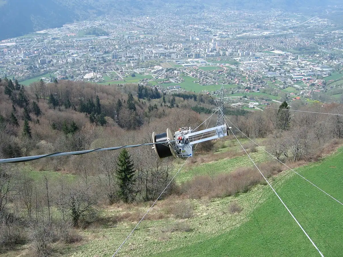
ADSS contains no metal, so its fittings create no conduction path and need no bonding, earthing, or surge protection of their own. The cable can share structures with circuits up to 500 kV. Crews avoid grounding labor, and the route avoids the stray-current corrosion paths that plague metallic attachments.
The dielectric benefit does not stop at the cable. Insulating attachment hardware keeps leakage currents from gathering near the support, which is exactly where dry-band arcing tends to ignite. The hardware cannot make the cable dielectric, but it can refuse to become the weak conductive link. That refusal is a safety feature.
For buyers, the benefit is practical rather than abstract. No bonding means no ground kits to install on every pole, no bond wires to corrode and re-tighten on maintenance rounds, and no earth-resistance acceptance tests on the fiber route. Over a multi-kilometer build, that removes one full trade from the crew schedule and one recurring defect class from the maintenance file.
Stopping Tracking and Dry-Band Arcing at Voltage
Near energized phases, the air around the cable sits at a floating charge called space potential. Contamination plus moisture turns the jacket surface conductive, leakage current dries a narrow ring, and the full potential strikes an arc across it. In the right conditions those arcs repeat hundreds of times per hour, carbonizing the jacket into conductive tracks.
Hardware selection respects two boundaries. Below about 12 kV of space potential, which covers lines up to roughly 35 kV, standard PE jackets have decades of service history. Between 12 and 25 kV, track-resistant AT jackets filled with alumina trihydrate quench arcs and leave non-conducting residue, and AT becomes the default around 110 kV lines and above. A detailed treatment of these boundaries is in this ADSS tracking field guide, and the arcing chemistry is unpacked in this dry-band arcing analysis.
The cost of ignoring the boundary is steep. On a badly placed 132 kV route, tracking can eat through a 1.5 mm PE jacket in 12 to 24 months. Replacing a tracked span typically runs 3 to 5 times the original installation cost. Hardware cannot compensate for a jacket chosen against the wrong field strength. What it can do is keep the support area clean: smooth profiles, no exposed sharp edges, and inserts that hold contamination off the jacket instead of grinding it in.
Weathering Defenses: UV Stability and Corrosion Control
Sunlight is the quiet enemy. Unstabilized polymer chalks and micro-cracks under ultraviolet exposure, and those cracks trap moisture and dirt that feed surface arcing. Jacket compounds therefore carry carbon black or chemical UV stabilizers, and insert rubbers are specified UV-resistant for the same reason.
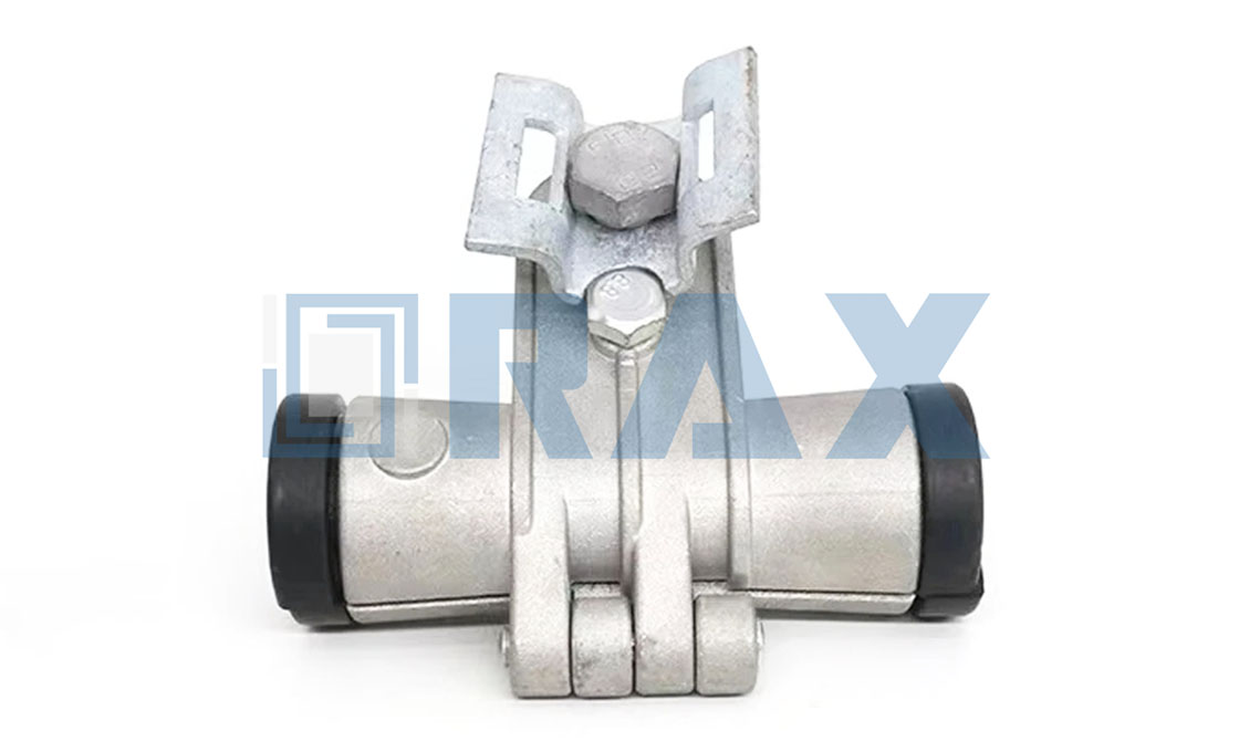
Metal parts fight their own weather. Hot-dip galvanizing to ISO 1461 protects steel brackets and bolts, aluminum alloy clamp bodies resist corrosion on their own, and hot forging gives load-bearing parts a dense, crack-free grain. The material list is short on purpose. Every added coating is one more layer that can fail.
Rod alloys follow the same discipline. ADSS preformed sets are drawn from aluminum alloy or aluminum-clad steel wire, which carry the cable’s tension without introducing the galvanic pairings that corrode at every wet junction. Production runs under an ISO 9001 quality system, the same framework that governs the forging and galvanizing upstream.
Specifying Hardware That Protects as Designed
Hardware earns its safety rating long before installation, at the drawing and forging stage. In our experience, the failures that surface in year five were decided at the ordering stage, when a cushion insert or a rod alloy was substituted to shave cost. RaxPower engineers fittings around the cable’s limits first, then around the price.
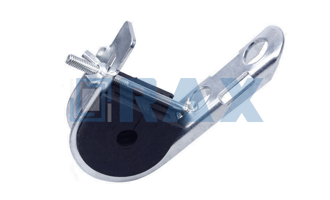
The checklist is short but non-negotiable. Match the clamp curvature to the cable diameter range, confirm insert material against site UV and temperature, and hold every assembly to the tension class of the span. Hardware that respects the cable’s limits lets every other safety feature do its job.
Bend Radius Limits Hardware Must Respect
Every ADSS datasheet states a minimum bend radius, commonly 10 times cable diameter at rest and 20 times under maximum tension. Inside that limit, fibers see acceptable macro-bending loss. Below it, attenuation creeps and the jacket takes a permanent set at the worst possible spot.
Hardware enforces the limit geometrically. Suspension clamps hold a built-in curvature matched to the cable diameter, dead-end loops keep generous storage bends clear of the pole, and downlead guides prevent sharp corners on the descent. A clamp set made for a 9 mm cable is not a cushion for a 16 mm one, because the curved shell itself would over-bend it.
Closure and downlead locations deserve equal care, since mid-span hardware is rarely where the tightest corner appears. Route changes, pole replacements, and splice loops are where ADSS cable hardware meets its tightest bends, so specify guide sizes alongside the clamps rather than improvising them on the pole.
Matching Safety Features to Span and Voltage
No single fitting carries every risk. The matrix below lines up each protection mechanism with the failure it removes and the condition that calls for it.
| Safety mechanism | Failure it protects against | Where it matters most |
|---|---|---|
| Helical rod dead-end grip, above 95% RTS | Tension concentration and strand stress | Terminal, angle, and tension towers |
| Cushioned suspension insert | Crush, cut-through, tracking at the support | Every suspension pole on shared power routes |
| Vibration damping, spiral or Stockbridge | Aeolian fatigue at the clamp lip | Spans beyond roughly 200 m in open terrain |
| Dielectric, non-bonded attachment | Grounding labor, stray current, induced paths | All ADSS builds, up to 500 kV shared structures |
| Jacket plan matched to space potential | Dry-band arcing and carbon tracking | Lines above roughly 35 kV, mandatory above 110 kV |
| Bend-radius-matched shells and loops | Macro-bending loss and permanent jacket set | Diameter transitions, downleads, and closures |
Treat the table as a screening tool, then confirm against the actual cable datasheet and the route’s space potential. The full fiber optic cable hardware range maps each family to cable diameters and span classes.
ADSS cable hardware safety features at a glance
ADSS cable hardware protects the cable through five mechanisms. Helical rod grips spread tension and hold above 95% of RTS. Cushioned suspension inserts prevent crush and absorb vibration at supports. Dampers cover spans beyond roughly 200 m, dielectric attachments remove bonding and grounding work, and hardware geometry keeps bends within 10 to 20 cable diameters.
Jacket-level protection adds UV stabilizers. Anti-tracking compounds apply when space potential at the attachment point passes roughly 12 kV, with AT the default around 110 kV lines and above.
Frequently Asked Questions About ADSS Hardware Safety
What do ADSS cable hardware safety features actually protect against?
Crush and abrasion at suspension points, bending fatigue at clamp lips, aeolian vibration fatigue along spans, electrical tracking near energized phases, ultraviolet and corrosion damage, and over-bending during routing. Each fitting family targets one or two of these failure modes rather than all of them at once.
Do ADSS fittings require grounding or bonding?
No. ADSS is fully dielectric, so its attachments create no conduction path and need no bonding, earthing, or surge protection. The cable can share structures with circuits up to 500 kV, which removes grounding labor and eliminates stray-current corrosion around supports.
When does an ADSS cable need an anti-tracking jacket?
Judge by space potential at the attachment point, not line voltage. Below about 12 kV, plain PE jackets serve for decades, which covers lines up to roughly 35 kV. From 12 to 25 kV, specify AT compound, and near 110 kV lines and above it becomes mandatory.
How much tension can a preformed dead-end grip hold?
Manufacturers rate quality preformed dead-ends above 95% of the cable’s rated tensile strength. Because tension spreads along the rod lay length, there is no single stress concentration point, which protects the aramid strength members doing the real work inside the cable.
How can I tell whether vibration protection is adequate?
Start with span length: below 200 m the cable’s self-damping usually suffices, while 200 to 400 m typically takes two spiral dampers, one per end. In service, watch OTDR traces for creeping attenuation and inspect the jacket at clamp lips for polish, chafing, or cracking.