
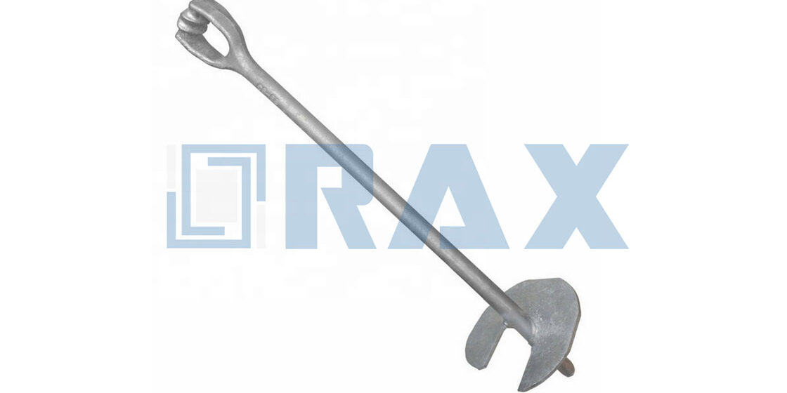
Field crews often waste hours switching between tooling for manual and machine-installed guy anchors. No-wrench screw anchors eliminate that redundancy by accepting a standard turning bar for manual operation or a power adapter for machine installation, all within the same assembly design. This versatility allows you to adapt to site constraints without compromising the foundation’s integrity.
Installation torque thresholds vary significantly based on rod diameter and soil density. The ultimate holding capacity of a screw anchor is directly proportional to the installation torque applied during driving, but this relationship requires strict adherence to a mandatory 5-degree alignment tolerance to ensure structural integrity. Furthermore, installers must account for a 10-20% capacity reduction when using hand installation methods compared to powered driving. Selecting the correct helix and rod combination remains essential to guarantee load test verification on the first attempt, while specific coating requirements must be met to achieve the desired corrosion warranty lifespan across different soil classes.
How Much Torque Is Needed for Strength
The ultimate holding capacity of a screw anchor is directly proportional to the installation torque applied during driving. Achieving the rated strength requires meeting specific torque thresholds dictated by the anchor’s physical dimensions and the in-situ soil properties.
The Physics of Torque-to-Tension Conversion
In the field of pole line hardware, the relationship between installation torque and ultimate capacity is governed by a linear correlation. As the helix of the anchor penetrates the soil, it encounters resistance; the rotational force required to overcome this resistance—measured as torque—is a direct predictor of the anchor’s future holding power. If an installation is terminated prematurely because the driving torque is too low, the anchor will fail to reach its rated strength. We utilize this principle to validate installation integrity; if the target torque isn’t reached, the anchor has not engaged enough soil mass to provide the necessary tension load for the guy wire or structural component.
It is critical to distinguish between installation torque and the operational tension of the guy wire. While installation torque ensures the anchor is set, the guy wire applies the working load. The installation torque value must exceed the calculated working load by a significant safety factor to account for soil creep and environmental variations. Our in-house load testing per IEC 120 standards confirms that anchors driven to the correct torque specification consistently outperform those merely “screwed in” until resistance is felt.
Anchor Sizing and Torque Thresholds
Torque specifications are not arbitrary; they are intrinsically linked to the rod diameter and helix size. Larger diameter anchors displace more soil and therefore require significantly higher installation torque to achieve their rated capacity. For instance, a standard no-wrench anchor with a 1-1/4″ rod diameter may require a maximum installing torque of up to 2300 ft.-lbs. to ensure full capacity. Exceeding this limit risks mechanical failure of the rod, while failing to reach it compromises the foundation.
To manage these high forces, the material integrity of the anchor rod is paramount. We employ hot-forging processes rather than casting for our critical hardware components. This manufacturing choice ensures the grain structure of the steel aligns with the torsional stress, allowing the rod to withstand the high twisting forces required for installation without shearing. Whether dealing with our 4″ standard helix or our larger 15″ configurations, the torque rating scales with the surface area of the helix, demanding durable equipment and precise monitoring to prevent under-driving or structural damage.
- Rod Diameter: Determines the maximum allowable torque before the steel yields.
- Helix Size: Larger helices increase soil displacement, demanding higher torque to achieve depth.
- Material Grade: Hot-forged steel provides superior torsional strength compared to cast alternatives.
Soil Density Variables and Driving Force
Soil density acts as the primary variable in the torque equation. In loose or sandy soils, an anchor may achieve significant depth with minimal torque, yet still lack the holding capacity required for heavy tension loads. Conversely, in dense clay or rocky substrates, the driving torque will spike rapidly as the anchor engages compacted soil. The required driving force is not a constant figure; it is a function of the soil’s shear strength.
This variability is why hand installation poses significant risks. Manual labor often fails to generate the sustained torque needed for optimal soil compression in dense earth, leading to under-performing anchors. We emphasize the use of mechanical drivers to ensure consistent force application. Additionally, strict adherence to a five-degree alignment tolerance is necessary during high-torque driving; misalignment in dense soil creates excessive bending moments that can snap the rod or strip the galvanizing, exposing the steel to corrosion. Monitoring the torque curve provides immediate feedback on soil density, allowing installers to verify they have reached a competent bearing strata.
| Component | Torque Specification | Installation Note | Quality Check | Benefit |
|---|---|---|---|---|
| Guy Wire & Anchor Fasteners | Refer to manufacturer datasheet; ensure 5-degree alignment tolerance | Mitigate hand-installation risks for optimal soil compression | Double-inspected by 10-person QC team | Maintains full structural strength and holding capacity |
| Turnbuckle Lock Nuts | Apply sufficient tension without over-tightening threads | Use calibrated torque wrenches for compliance | SGS verified structural integrity | Prevents thread damage and structural loosening |
| Hot-Forged Hardware | Aligned with ASTM A123/A153 galvanizing standards | Leverage hot-forging superiority over casting | In-house load testing per IEC 120 | Superior strength and precision under load |

How No-Wrench Anchors Drive Into Soil
The no-wrench anchor design relies on a specialized “eye rod” configuration to drive high torque and soil displacement without traditional wrenches, bypassing the need for secondary turning tools during installation.
The Mechanics of Tool-Free Rotation
In utility installations, the primary bottleneck is not the drilling of the initial pilot hole, but the application of sufficient rotational force to sink the helix into dense clay or compacted soil. Traditional screw anchors often require a secondary setup where an installer must manually hold a heavy spanner (wrench) against the anchor rod to prevent it from spinning backward while another person turns a bar. This two-person, tool-heavy process increases labor costs and creates alignment issues.
A no-wrench anchor eliminates this mechanical conflict by integrating the turning mechanism directly into the anchor rod itself. The anchor features a forged eye at the top of the shaft, specifically sized to accept a T-bar or turning handle. This configuration allows the installation crew to apply massive torque directly down the axis of the screw without any external clamping force. The turning action drives the helix downward through sheer mechanical advantage.
Soil Displacement and Torque Transfer
- Axial Torque Application: Because the turning force is applied directly to the eye rod, the torque transfers instantly to the welded helix plates. There is zero energy lost to friction or slipping, which is common with loose grip wrenches.
- Helical Pitch and Penetration: As the anchor turns, the threads act like an inclined plane moving through the ground. In soil classes ranging from sandy loam to stiff clay, this continuous displacement requires significantly less peak driving force compared to driven spike anchors that bluntly displace soil radially.
- Self-Aligning Stability: The direct-drive nature of the no-wrench design keeps the anchor perfectly plumb (vertical). When a worker applies force to the eye rod, the anchor bites evenly into the soil strata, preventing the “wobble” and cross-threading that frequently occur when trying to wrench a rod that has already started binding in hard soil.
Power vs. Manual Installation Capabilities
While designed for manual speed, the structural integrity of a quality no-wrench anchor—often fabricated via drop-forging rather than casting—allows it to withstand extreme mechanical stress. When the turning eye is fitted with the correct adapter, these anchors can be driven by rotary drill rigs or helical pile drivers.
This compatibility is critical for large-scale solar farm foundations or extensive transmission line guying. A crew can switch smoothly between hand-tightening for final tensioning and using a hydraulic impact driver for rapid deep-soil penetration. The ability to reach installation torques well above 2,000 ft.-lbs. (approx. 2,700 N·m) ensures that the anchor achieves its maximum load-bearing capacity in deep, high-density soil layers without snapping the drive mechanism.
Load Capacity Across Different Soil Types
A pole anchor’s rated load capacity is not a fixed number; it is a dynamic variable strictly dependent on soil density and cohesion. Correct engineering design must factor in soil class variations to prevent catastrophic under-engineering.
The Soil-Dependence of Pull-Out Resistance
While steel anchors are manufactured to precise yield strength standards, their real-world holding power is dictated entirely by the ground they are embedded in. A helical anchor installed in dense clay will exhibit vastly different performance metrics compared to one installed in loose sand or organic topsoil.
Utility engineers frequently make the critical error of relying solely on the steel’s tensile rating during the procurement phase. However, the soil’s bearing capacity is almost always the limiting factor. If the surrounding soil cannot exert enough frictional resistance against the helix plates, the anchor will simply pull out of the ground long before the steel itself reaches its breaking point.
Performance Variations by Soil Classification
Understanding how different soil classes interact with anchoring hardware is essential for maintaining grid integrity. The following breakdown highlights the specific engagement mechanics required for each primary soil type:
- Cohesive Soils (Clay & Silt): These soils provide exceptional holding power due to high shear strength and adhesion. In highly cohesive clay, a standard helix anchor achieves maximum pull-out resistance at relatively shallow depths. Engineers must be careful, however, to ensure the helix pitch is deep enough to anchor into a stable sub-layer rather than loose topsoil.
- Granular Soils (Sand & Gravel): Granular materials rely primarily on frictional resistance. While compacted gravel offers excellent support, loose or medium-density sand requires deeper installation or larger helix diameters to compensate for the lack of cohesion. Failure to increase the embedment depth in sandy environments often results in a 30% to 50% reduction in effective load capacity.
- Organic Soils (Peat & Fill Dirt): These materials are structurally unreliable for permanent power infrastructure. Organic matter decomposes over time, causing massive shifts in soil density and volume. Anchors placed in fill dirt or peat must never rely solely on surface friction; they require extension rods to bypass the unstable upper layers and secure deep into competent native soil.
Installing a “high-capacity” anchor without verifying the specific soil class is a leading cause of premature line failures. Always consult a geotechnical report. If the report indicates loose topsoil over bedrock, a standard screw anchor is useless unless extended all the way to the rock face.
Mitigating Low-Capacity Soil Conditions
When faced with poor soil conditions that threaten to drop load capacities below safety thresholds, the industry utilizes specific engineering adjustments. Extending the anchor rod past the soft stratum to reach a denser, more cohesive layer is the most reliable method for restoring holding power.
Additionally, increasing the diameter of the helix plates can drastically improve performance in granular soils. By expanding the surface area that pushes against the earth, the anchor generates higher frictional resistance. For extreme applications involving significant lateral loads, using multiple helix plates on a single shaft allows the anchor to distribute the tension across a broader vertical plane of soil.
In regions known for shifting clay or expansive soils, always design your guy wire anchoring system with a minimum safety factor of 2.5x. The soil movement over decades can slowly degrade the anchor’s grip, so leaving a wide margin between expected load and theoretical failure is non-negotiable for utility longevity.
Choosing the Right End Fitting Design
Selecting the Correct Fitting Geometry for Rotational Load Management
When specifying end fittings for guy wires and tensioned cables, the most frequent engineering error is selecting a rigid termination for a system requiring multi-axis rotational flexibility. For overhead line infrastructure subjected to asymmetric wind loading or line tension, the fitting must act as a swivel to prevent torsional stress from twisting back into the cable strands. If a standard U-bolt clamp or fixed eye is used where a swivel is required, the constant torque will degrade the structural integrity of both the hardware and the conductor over time.
Engineers should prioritize triple-eye (triple-plate) designs for high-tension distribution applications. The central eye connects to the structure, while the outer two eyes provide distinct anchor points for the turnbuckle body and the thimble-equipped wire rope. This geometry ensures that the load remains perfectly aligned with the centerline of the hardware, even if the guy wire settles or shifts during installation. Without this design, the turning force applied during tensioning locks the hardware in place, transferring mechanical strain directly into the pole or cross-arm rather than the ground anchor.
- Torsional Relief: Triple-eye fittings allow independent rotation of the turnbuckle body relative to the wire strand, neutralizing rotational forces before they damage the conductor.
- Load Alignment: The geometry maintains a straight-line pull from the anchor point through the turnbuckle, minimizing lateral bending moments on the steel hardware.
- Installation Tolerance: These fittings easily accommodate minor discrepancies in hole drilling on poles or cross-arms without compromising the structural bite of the hardware.
Evaluating Compatibility with Turnbuckle Toggles
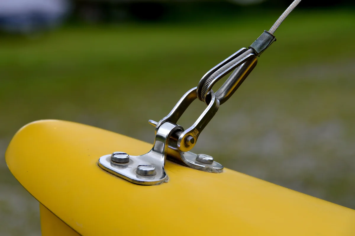
The selection of the end fitting is intrinsically linked to the toggle mechanism of the turnbuckle. While a standard toggle provides excellent rigidity for static structures, dynamic environments—such as those found in Southeast Asian monsoon regions or Russian extreme cold grids—often require specialized toggles that lock securely against vibration. Ensure the eye diameter of your chosen fitting matches the toggle shank precisely; an oversized eye creates dangerous slop, while an undersized eye prevents proper insertion of the cotter pin.
For applications utilizing No-Wrench screw anchors, the end fitting must be robust enough to handle the high-breaking loads generated by deep soil penetration. The connection point between the anchor rod and the guy wire needs to withstand massive torque-to-tension conversion without stripping. Using a drop-forged triple-eye fitting with a standardized hole diameter ensures that the energy applied during installation translates directly into holding power, rather than deforming the metal connection point itself.

No-Wrench Anchors vs. Traditional Options
Field Efficiency and Precision Comparison
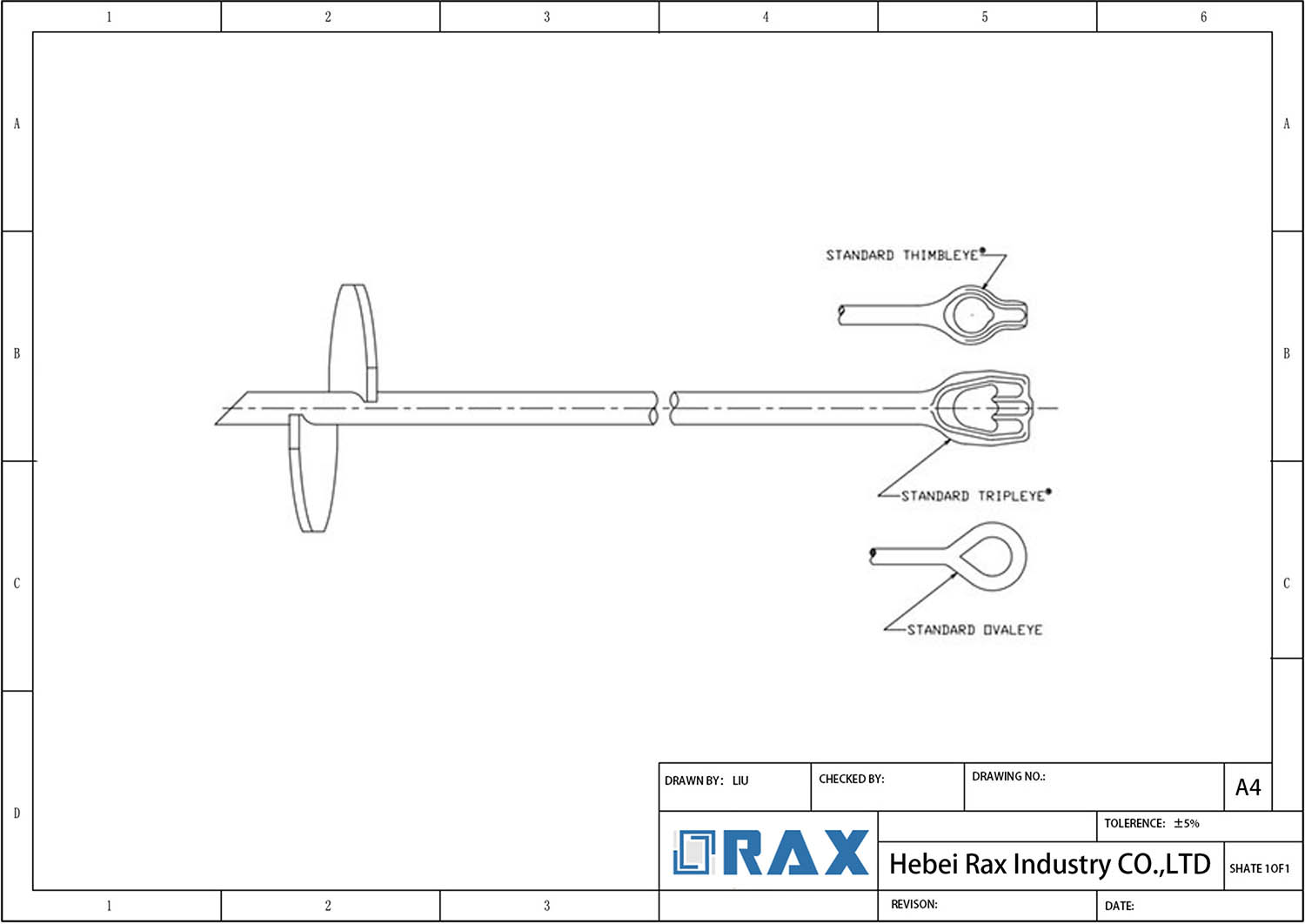
Traditional helical pile installation relies heavily on precise torque application using specialized equipment. This equipment reliance introduces significant logistical bottlenecks, such as the need to transport heavy wrenches or hydraulic drives, which increases site congestion and requires skilled operators. No-wrench anchors fundamentally shift this paradigm by utilizing large eye rods (such as THIMBLEYE® or TRIPLEYE® configurations) that allow contractors to use a standard turning bar or compatible power augers, thereby eliminating the need for specialized torque tools.
This transition from driven wrenchs to manual or semi-powered screwing drastically reduces mobilization time. For utility contractors managing extensive right-of-way projects, the ability to deploy multiple crews with lightweight tools rather than a single crew operating a massive excavator-mounted driver translates directly into lower labor costs and faster project turnaround.
- Tooling Logistics: Traditional methods require renting or shipping heavy hydraulic drivers. No-wrench systems only require a simple steel turning bar and an adapter, keeping site overhead minimal.
- Operator Flexibility: Manual driving via a turning bar allows for intuitive “feel” of the soil, whereas mechanical driving can sometimes strip threads if torque limits aren’t perfectly calibrated by the operator.
- Power Auger Compatibility: Modern no-wrench designs feature standardized large-eye connections, enabling them to be rapidly powered up by standard hole-boring machines, bridging the gap between manual speed and mechanized force.
| Comparison Aspect | Rax Power No-Wrench Anchors | Traditional Alternatives | Engineering Advantage |
|---|---|---|---|
| Manufacturing Method | Hot-forging process | Conventional casting | Superior structural strength and material precision |
| Dimensional Accuracy | Manufacturing precision ensures consistent field performance across different product lines. The hot-forging process optimizes structural strength and material integrity. | Variable manual manufacturing tolerances | Guaranteed fit and consistent field performance |
| Corrosion Protection | Hot-dip galvanizing; >85 microns (ISO 1461, ASTM A123/A153) | Standard coatings with varying thickness | Extended service life in harsh soil and environmental conditions |
| Installation Precision | Defined torque requirements; 5-degree alignment tolerance | Uncontrolled hand installation | Optimal soil compression and maximum holding capacity |
| Quality Assurance | 10-person QC team; double-review; SGS verified | Basic single-stage inspection | Certified structural integrity and load safety |
Rod Diameter and Sizing Guidelines
Correlating Rod Diameter with Load Ratings
Rod diameter is the primary determinant of an earth anchor’s ultimate load capacity and its resistance to torsional stress during installation. In standard B2B applications for utility and solar foundations, rod diameters typically scale from 0.75 inches (3/4″) for lighter loads to 1.25 inches (1-1/4″) for high-capacity tensioning. Selecting the correct diameter relies on matching the expected tensile pull-out force against the yield strength of the specific rod material.
Standard Sizing Specifications
Utility contractors must account for the relationship between rod thickness, helix configuration, and soil class when estimating system performance. The following industry-standard specifications highlight how dimensional changes affect maximum allowable installation torque and structural integrity:
- 3/4″ Diameter Rod: Commonly paired with a 6-inch helix, this smaller rod is optimized for lower-tension scenarios such as solar ground mounts in soft soils. It generally supports a maximum installation torque of approximately 400 ft.-lbs., requiring careful driving procedures to prevent bending.
- 1-1/4″ Diameter Rod: Designed for heavy-duty power line guy wires or extreme environment projects, this robust shaft can withstand significantly higher mechanical stress. It supports a maximum installation torque of up to 2,300 ft.-lbs., allowing it to be driven into dense, rocky soil strata without compromising the anchor’s structural core.
Extension Rod Engineering Standards
For deeper installations where standard rod lengths are insufficient, extension rods are utilized to bridge the gap between the surface and the target bearing layer. The connection mechanism between the primary anchor and the extension rod must maintain perfect concentricity to avoid cross-threading or galling under high-torque loads.
In no-wrench screw anchor configurations, extensions are engineered to accommodate both manual turning bars and machine adapters. Because torque transmission degrades as length increases, a 1-1/4″ diameter extension requires a highly rigid connection interface—often featuring THIMBLEYE® or TRIPLEYE® style large openings—to distribute the turning force evenly across the entire circumference of the rod.
Coatings That Ensure Long-Term Durability
Hot-Dip Galvanizing Compliance with ISO 1461
The durability of pole line hardware and earth anchors relies entirely on the integrity of their corrosion protection. Industry-standard hot-dip galvanizing must strictly adhere to ISO 1461 (and ASTM A123/A153 for varying regional utilities) to guarantee long-term structural survival.
Proper galvanization is not merely a surface paint job; it creates a metallurgical bond between the steel substrate and the zinc coating. This reaction forms a series of zinc-iron alloy layers that are inherently more durable than surface-applied coatings. Any deviation from this standard leaves utility infrastructure highly vulnerable to premature rusting, especially in aggressive soil compositions.
Our rigorous hot-dip galvanizing process ensures a smooth, bright finish that completely encapsulates critical areas, including internal threads and complex geometries found in guy clamps and helical anchor shafts. We prioritize total coverage to prevent localized failure points where moisture can easily penetrate bare metal.
Coating Thickness Standards for Corrosion Resistance
Thickness is the primary metric dictating the lifespan of galvanized hardware. Thinner coatings erode rapidly when exposed to continuous environmental stress, leading to sudden structural failure. According to strict ISO 1461 requirements, the mean coating thickness for heavy-duty industrial fasteners and anchors must exceed a highly specific baseline.
- Standard Industrial Baseline: Typically ranges between 55 to 75 microns for lighter gauge materials. While this satisfies basic municipal applications, it offers minimal longevity in corrosive terrains.
- Rax Power Premium Standard: Our products achieve a mean coating thickness exceeding 85 microns. This dense layer provides a massive buffer against corrosion, significantly extending service life in harsh environments.
By enforcing an 85+ micron standard, we ensure that even if minor surface abrasions occur during the demanding installation process—such as screwing an anchor deep into rocky soil—the underlying zinc barrier remains thick enough to protect the steel core.
Durability Metrics for Extreme Environmental Conditions
Hardware deployed in extreme environments faces chemical aggression from acidic soils, constant salt spray exposure near coastal regions, or severe freeze-thaw cycles. The interaction between the zinc coating and these elements determines the asset’s viability. High-quality galvanization functions by sacrificially corroding itself to save the steel underneath.
In our engineering experience, the superior density of an 85-micron coating drastically slows down this sacrificial rate. For projects targeting markets like Russia, South America, or Southeast Asia, we customize our galvanizing protocols to meet local utility tender requirements. This ensures that turnbuckles, cross arms, and anchor rods survive decades of exposure without necessitating costly replacements.
Furthermore, our commitment to double-review inspection guarantees that no product ships with incomplete zinc coverage. By combining strict ISO compliance with superior thickness metrics, Rax Power ensures that your pole line infrastructure maintains peak mechanical strength throughout its operational lifecycle.
Conclusion
Getting the right torque isn’t just about brute force. You must match the rod diameter and driving energy to the specific soil class, or the holding power simply won’t exist. And don’t overlook the coating—hot-dip galvanizing to ISO 1461 isn’t optional for Class 5 soil if you want that anchor to last a decade without rusting off underground. Spec the right materials first.
- Verify the ground density before selecting the anchor size.
- Ensure installation torque matches the rated tension on the charts.
- Reach out to our engineering team to validate your site load requirements.
Frequently Asked Questions
What is the exposed height after installation?
The exposed height depends on the total anchor length and the depth to which it is driven, leaving enough shaft for the guy attachment. Installers must calculate the burial depth required to achieve the holding capacity while reserving sufficient length for hardware connections. Proper estimation prevents the anchor from being buried too deep or remaining too high.
How is adjustment range calculated?
Adjustment range is the usable thread length available for tensioning the guy wire after installation. It is calculated by deducting the fixed connection length and the required burial depth from the total anchor length. Ensuring adequate take-up range is necessary to accommodate initial stretching and future maintenance re-tensioning.
Can I extend the anchor depth?
Yes, depth can be extended using couplers to attach additional anchor rods when deep bearing strata are required. Extensions allow the helix to penetrate through soft surface layers to reach stable soil beneath the surface. It is crucial to ensure that all couplings are tightened securely to maintain the structural integrity of the shaft.
Are custom lengths available?
Manufacturers typically provide custom length options to accommodate specific project requirements or varying soil depths. Providing detailed specifications allows for the production of anchors that fit unique installation scenarios without needing field modifications. Custom solutions ensure optimal performance and compatibility with existing infrastructure.
Does hot-forging improve strength?
Yes, hot-forging significantly improves the grain structure of the steel, offering superior strength compared to traditional casting methods. This process enhances the material’s ductility and impact resistance, which is critical for components under high load. At Raxpower, we utilize hot-forging to ensure that every anchor meets rigorous durability and safety standards.