
Les lignes de transmission ne cèdent pas à cause de la gravité ; elles cèdent à cause de la fatigue. Vibrations éoliennes grignotent les points de contrainte du conducteur, transformant un actif de milliards de dollars en passif en moins d'une décennie. L'analyse des défaillances sur le terrain par Rax Industry confirme qu'ignorer cette micro-vibration au niveau des serre-câbles de suspension est la cause première de mise hors service prématurée du conducteur.
Des tiges d'armure préformées correctement spécifiées offrent un niveau de rétention de résistance d'au moins 95 % de celui du conducteur original, garantissant que l'intégrité mécanique de la ligne n'est pas compromise aux points de suspension critiques. Nous examinerons comment les compositions en alliage d'aluminium protègent les conducteurs ACSR et AAAC contre l'abrasion et la flexion, ainsi que pourquoi l'alignement du sens de hélice de la tige est non négociable pour la longévité. Vous apprendrez comment sélectionner un système de suspension qui atténue la fatigue due aux vibrations plutôt que de simplement la masquer.
Qu'est-ce qu'une tige d'armure ?
Une tige d'armure est une tige hélicoïdale préformée conçue pour s'enrouler autour d'un conducteur, répartissant la contrainte de suspension afin de prévenir la fatigue et l'abrasion.
La physique de la structure en spirale hélicoïdale
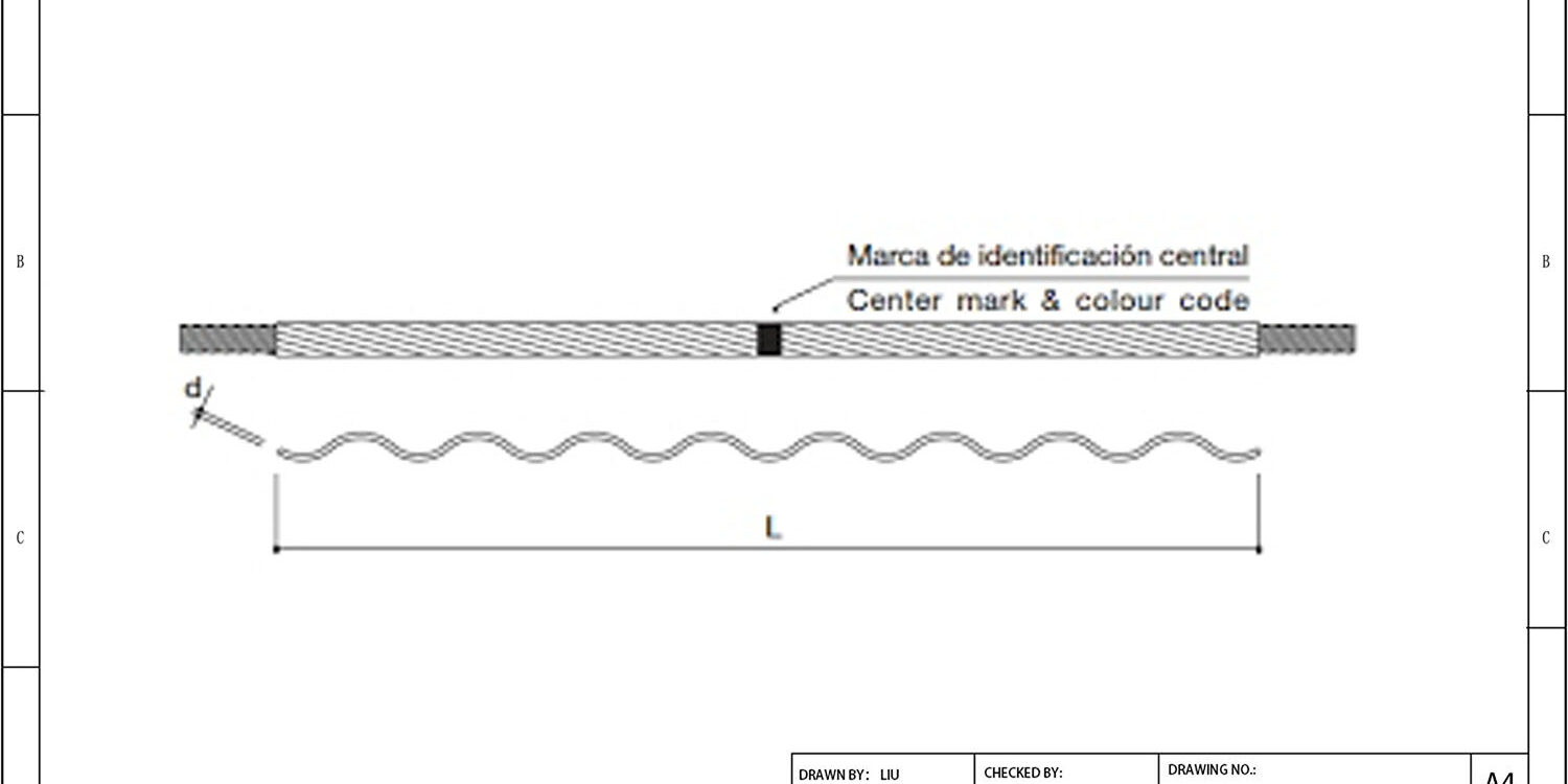
Visuellement, une tige d'armure ne ressemble pas à du matériel standard ; elle ressemble à un ressort étiré ou à un tire-bouchon. Cette géométrie hélicoïdale “ préformée ” est au cœur de son ingénierie. Contrairement aux serre-câbles traditionnels à boulons qui pinceraient le conducteur en des points spécifiques, la structure en spirale maintient un contact continu sur toute sa longueur. Une fois installée, les brins de l'hélice s'emboîtent pour créer une prise unifiée qui répartit la charge uniformément sur la surface du conducteur.
Voici comment visualiser cela : un serre-câble boulonné concentre la pression sur deux côtés du fil, créant des pics de contrainte. La structure en spirale agit comme une attelle, épousant toute la circonférence. Cette conception permet à l'ensemble de résister aux vibrations éoliennes — oscillations haute fréquence induites par le vent — sans grippage ni entaille dans le conducteur. Du point de vue de la fabrication, garantir que cette forme hélicoïdale conserve sa “ mémoire ” est critique. Si la tige perd sa courbure préformée, elle ne peut pas maintenir la pression de serrage nécessaire. Nous comptons sur des machines de formage automatisées pour garantir que chaque tige quitte l'usine avec le pas hélicoïdal précis requis pour s'enrouler solidement sur le câble sans déformation.
Composition matérielle de l'alliage d'aluminium
Le choix du matériau n'est pas arbitraire ; il est dicté par l'électrochimie. Les tiges d'armure sont généralement fabriquées en alliage d'aluminium haute résistance. Ce choix est motivé par la nécessité de compatibilité galvanique avec le conducteur lui-même. Puisque la plupart des conducteurs aériens (AAC, AAAC, ACSR) sont à base d'aluminium ou recouverts d'aluminium, l'utilisation d'une tige en acier créerait une réaction entre métaux dissemblables. En présence d'humidité, l'acier et l'aluminium agiraient essentiellement comme une batterie, entraînant une rapide corrosion galvanique du conducteur.
En alignant l'alliage d'aluminium de la tige avec celui du conducteur, nous garantissons la stabilité électrochimique, empêchant la corrosion qui pourrait compromettre l'intégrité de la ligne dans plusieurs décennies. De plus, l'alliage doit être suffisamment doux pour ne pas rayer le conducteur lors de l'installation, mais assez dur pour résister aux impacts de débris ou de glace. Nos protocoles de contrôle qualité impliquent des analyses rigoureuses de la composition chimique afin de s'assurer que les tiges en alliage satisfont à ces deux exigences de dureté et de conductivité.
L'ingénierie de l'adéquation des diamètres
Il n'existe pas de tige d'armure “ universelle ”. La relation entre le diamètre intérieur de la tige et le diamètre extérieur du conducteur est un jeu à somme nulle. La tige hélicoïdale est fabriquée avec un diamètre intérieur légèrement inférieur à celui du conducteur qu'elle est censée protéger. Ce “ sous-dimensionnement ” est intentionnel ; lorsque la tige est enroulée autour du conducteur, elle est forcée de s'ouvrir, créant une tension semblable à un ressort qui serre solidement l'ensemble.
- Trop grand : Si le diamètre de la tige est trop grand, la force de serrage nécessaire ne se développe jamais. La tige restera lâche sur le conducteur, incapable d'atténuer les vibrations et risquant de glisser hors de position.
- Trop petit : Si la tige est trop petite, les forces d'installation deviennent excessives. Cela peut endommager les brins extérieurs du conducteur lors du processus d'enroulement ou surcharger le matériau de la tige d'armure, entraînant des fissures de fatigue prématurées.
C'est pourquoi la spécification précise est non négociable. Nous fournissons des tableaux de dimensionnement détaillés qui cartographient des codes de tiges spécifiques à des diamètres de conducteurs exacts. Selon notre expérience, de nombreuses défaillances sur le terrain remontent à des substitutions “ suffisantes ”. La norme de l'industrie exige un ajustement précis, et nous adhérons à des contrôles de tolérance stricts pour garantir que lorsqu'une de nos tiges est spécifiée pour un conducteur, l'ajustement serré offre une protection optimale sans compromettre la structure du câble.
| Caractéristique | Spécifications | Avantage |
|---|---|---|
| Fonction principale | Protection mécanique et amortissement des vibrations pour les conducteurs aériens | Empêche la défaillance par fatigue et l'abrasion aux points de suspension |
| Composition du matériau | Alliage d'aluminium haute résistance avec brins hélicoïdaux préformés | Assure la compatibilité avec les matériaux du conducteur et la résistance à la corrosion |
| Méthode d'Installation | Application hélicoïdale manuelle ou motorisée sans outils | Fournit une répartition uniforme de la contrainte et une prise sécurisée sur divers diamètres |
| Normes de conformité | IEC 61284 / ASTM F719 tested for mechanical strength | Guarantees reliability under extreme environmental loads and vibrations |
| Durée de vie | Designed for 40-50 years of maintenance-free operation | Reduces long-term OPEX by eliminating frequent hardware replacements |

Pourquoi avez-vous besoin de tiges d'armure
Armour rods act as a critical mechanical buffer for overhead conductors, protecting expensive aluminum strands from fatigue and abrasion at suspension points.
In the harsh environment of overhead power lines, conductors are subjected to relentless physical stress. An armour rod serves as a hardened sleeve that covers the vulnerable transition zone where the rigid hardware meets the flexible conductor. This component is not merely an accessory; it is the primary defense mechanism against the two most common causes of premature line failure: aerodynamic vibration and structural friction.
Prévention de la fatigue par vibrations éoliennes
Even in moderate wind conditions, overhead lines experience a phenomenon known as Aeolian vibration. This occurs when steady wind flows across the line, creating vortices that induce a standing wave pattern on the conductor. Think of this like air blowing over the opening of a bottle to create a musical note—the conductor “sings” in specific frequencies.
While spiral vibration dampers are designed to absorb energy further down the span, they cannot fully mitigate the high-frequency oscillations right at the suspension point. Without protection, these constant micro-movements cause the individual aluminum strands of the conductor to bend back and forth until they undergo metal fatigue. An armour rod mitigates this by stiffening the conductor temporarily over its length. By increasing the rigidity of the protected section, it shifts the resonant frequency out of the problematic range, effectively stopping the fatigue process before it starts.
- Vortex Shedding: Wind creates alternating pressure waves that lift the conductor up and down.
- Fatigue Failure: Rapid bending at the clamp edge cracks aluminum strands.
- Rigidity Buffer: The pre-formed armour rod locks strands together to resist localized bending.
Répartition de la contrainte au point de suspension
The suspension clamp is responsible for holding thousands of pounds of tension. When a clamp applies direct pressure onto the soft aluminum strands of a conductor, it creates a massive concentration of stress. Over time, this crushing force permanently deforms the wires, reducing the overall cross-sectional area and electrical carrying capacity of the line.
Effective load distribution relies on the specific mechanical interaction between the armor rod and the conductor. An armour rod acts as a specialized load distributor. Because it is manufactured with a slightly smaller inner diameter than the conductor itself, it creates an interference fit and clamping force. When the suspension clamp grips the armour rod rather than the conductor directly, the immense mechanical tension is spread evenly across the surface of the rod. This distributes the crushing force across dozens of contact points instead of just a few tight grooves.
- Pressure Distribution: Spreads the clamp’s grip over a wider surface area.
- Strand Preservation: Prevents the crushing and flattening of delicate outer aluminum wires.
- Structural Integrity: Maintains the geometric shape of the conductor under heavy tension.
Protection contre l'abrasion de surface
During the installation phase, conductors are pulled through pulleys and past guide wires. This process subjects the conductor to severe frictional forces that can strip away the protective oxide layer and abrade the aluminum strands. Once the outer layer is compromised, the exposed inner steel core (in ACSR conductors) is highly susceptible to rapid corrosion, leading to catastrophic line failure years later.
Furthermore, the electrical clearance between the hard hardware and the wire creates microscopic movement during storms. This fretting action generates conductive dust that can bridge gaps and cause flashovers. The armour rod provides a sacrificial, highly abrasion-resistant barrier that takes the brunt of both installation friction and long-term operational rubbing. In our engineering assessments, we consistently find that lines installed with properly sized armour rods require significantly less maintenance intervention over a 40-year lifecycle compared to those relying solely on bare hardware.
- Installation Friction: Protects wires from damage during pulling and stringing operations.
- Fretting Corrosion: Stops wear caused by wind-induced rubbing between the wire and the clamp.
- Oxide Layer Defense: Preserves the natural corrosion resistance of the conductor surface.

Où utiliser des tiges d'armure
Zones d'installation principales sur les lignes de transmission
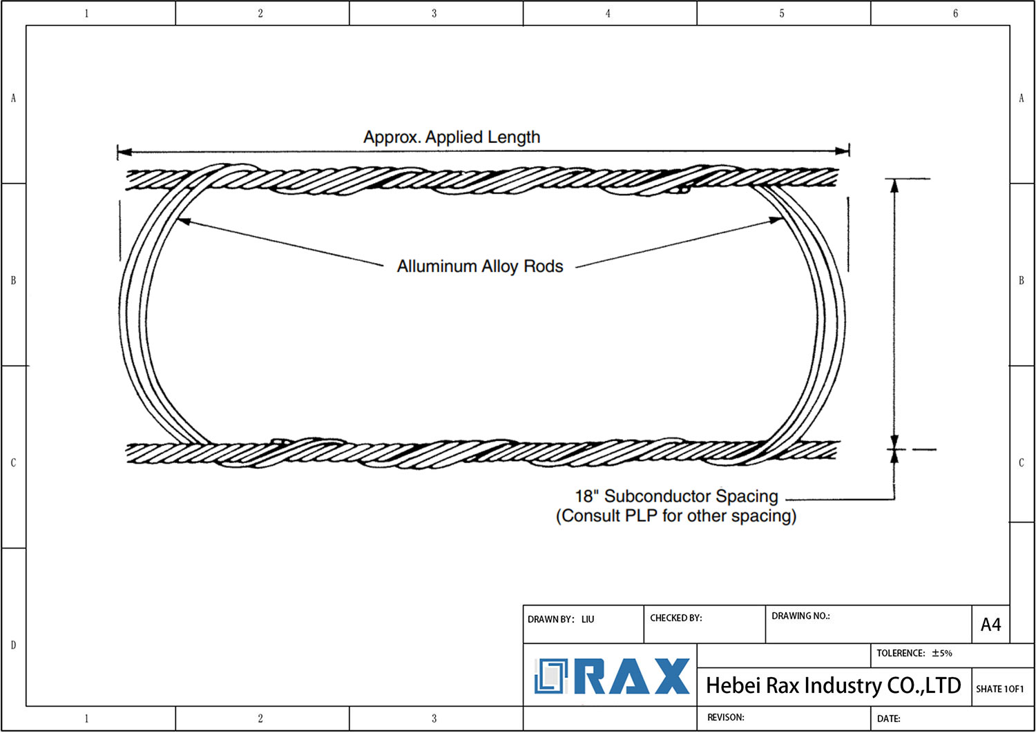
The most critical application for preformed armour rods is at mechanical suspension points where the overhead conductor is clamped to suspension hardware. Without these rods, the rigid metal grip of the clamp digs into the aluminum strands, creating high-stress concentration zones that lead to rapid fatigue and structural failure. By wrapping a helical aluminium alloy rod around the conductor before installing the suspension clamp, you effectively distribute the crushing load across a much wider surface area.
This is particularly vital for All-Aluminium Alloy Conductors (AAAC) and Aluminum Conductor Steel Reinforced (ACSR) lines. In these systems, the exterior strands are pure aluminum or aluminum-clad steel, which are significantly softer than the galvanized steel core. The armour rod acts as a sacrificial buffer, ensuring the internal steel core remains uncompromised while the outer strands are protected from abrasion and bending stress.
Compatibilité des matériaux de conducteur et dimensionnement
Correct deployment requires matching the armour rod material to the conductor type. For phase conductors made of aluminum alloys, using a standard aluminium alloy armour rod is standard practice to ensure galvanic compatibility and prevent corrosion between similar metals. Conversely, for overhead ground wires (OPGW) or conductors with an aluminum-clad steel exterior, an aluminium-clad steel armour rod is necessary to maintain mechanical integrity under high-tension loads.
The sizing is not generic; it must precisely match the nominal diameter of the cable. An oversized rod will create loose gaps allowing vibration-induced chafing, while an undersized rod cannot cover the full strand area, leaving vulnerable sections exposed to the suspension clamp’s bite.
Réseaux de distribution et branchements de service
Beyond high-voltage transmission, these components are essential in medium-voltage distribution networks and overhead service drops. In these configurations, the tension is lower but the frequency of bends and twists is higher due to shorter span lengths and frequent attachment points. Armour rods here prevent “kinking” of the stranded wire during installation and protect against the wear caused by constant wind-sway interactions with nearby structures like poles and cross-arms.
| Application Scenario | Engineering Function | Failure Mode Prevented | Type d'installation | Long-Term Value |
|---|---|---|---|---|
| Suspension Points | Distributes bending stress & increases grip area | Conductor fatigue & fretting wear | Preformed Helix (Hand-wound) | Extends conductor life under dynamic loads |
| Damaged Sections | Restores mechanical strength of strands | Progressive strand breakage | Spiral Wrap (Preformed) | Maintains ampacity and tension integrity |
| Dead-End Attachments | Provides cushioning against hardware contact | Abrasion & cutting at interface | Integrated with grips | Prevents stress concentration failures |
| Heavy Span Areas | Adds mass and stiffness for damping | Aeolian vibration resonance | Matched rod length to frequency | Ensures grid reliability in wind zones |

Comment choisir la bonne tige d'armure
Compatibilité et correspondance des matériaux
Selecting the appropriate armor rod begins with aligning the rod’s material properties with the conductor’s metallurgy. Armor rods are constructed from materials that must match the strand to which they are applied to prevent galvanic corrosion and ensure uniform mechanical performance.
- Aluminum Conductors: For All-Aluminum Alloy Conductors (AAAC) or pure aluminum strands, utilize preformed rods manufactured from aluminum alloy.
- Steel-Reinforced Conductors: For Aluminum Conductor Steel Reinforced (ACSR) lines, the rod must be engineered to interface correctly with the aluminum outer strands without damaging the core.
- Fiber Optic Integration: When used with optical ground wires or ADSS cables, specific aluminum-clad steel designs are often required to maintain both mechanical grip and electrical grounding integrity.
Always verify the exact conductor metallurgy before procurement. Mismatching materials can lead to accelerated corrosion at the contact points, significantly reducing the lifespan of the transmission line hardware.
Tolérance de diamètre et configuration hélicoïdale
Beyond material, the physical dimensions of the rod—specifically its internal diameter relative to the conductor—dictate the effectiveness of stress distribution. A properly selected helical armour rod acts as a flexible sleeve, distributing suspension clamping pressure over a broader area of the cable.
- Precise Fitment: The rod must slide onto the conductor with slight resistance but no forceful deformation of the wire strands. Too loose, and vibration fatigue continues; too tight, and you crush the aluminum strands, compromising tensile strength.
- Helix Pitch: The spiral pitch should align with standard industry tolerances for the specific voltage class, ensuring the rod holds its shape under high wind loads and thermal expansion.
Do not attempt to retrofit an armour rod designed for a smaller gauge onto a larger conductor. Even a minor mismatch can create uneven pressure points, leading to premature failure of the line hardware during severe weather events.
Conclusion
Mitigating aeolian vibration requires strict adherence to the correct material specifications and dimensional alignment. Our engineering teams have seen countless premature failures stem from mismatched suspension clamps or ignored fatigue limits. You must verify that your armor rods meet relevant aluminum alloy standards and align perfectly with your specific conductor diameter. This prevents the spiral helix structure from slipping under load, ensuring consistent stress distribution across the anchor point. Correct installation torque requirements are equally critical to avoid damaging the aluminum alloy composition during deployment.
- Reach out to our engineering group for technical clarification on these specs without any commercial obligation, allowing you to validate your design choices against our manufacturing data.
Proper implementation of these protective measures ensures long-term reliability and minimizes maintenance costs. To ensure your specific project requirements are met, we invite you to consult our technical experts.
Questions fréquemment posées
En quoi les tiges d'armure diffèrent-elles des serre-câbles standards ?
Standard clamps often create localized stress points that can crush or deform conductor strands. Armor rods use a helical design to distribute pressure uniformly along the conductor’s surface. This prevents strand breakage and maintains the electrical integrity of the line over time.
Les tiges d'armure sont-elles adaptées à tous les types de conducteurs ?
Armor rods are designed for ACSR and aluminum conductors but may not be compatible with Alumoweld or steel ground wires. Each conductor type has unique structural properties that require specific hardware configurations. Always verify compatibility with engineering standards before procurement.
Les tiges d'armure éliminent-elles le besoin d'amortisseurs ?
No, armor rods and vibration dampers serve complementary but distinct functions. Armor rods protect against abrasion and local stress, while dampers absorb vibrational energy. In many utility applications, both components are installed together for comprehensive protection against wind-induced oscillations.
Quelle est la durée de vie attendue des tiges d'armure ?
High-quality armor rods are engineered for a service life of 40 to 50 years under normal operating conditions. Their durability relies on proper installation and adherence to material specifications like ASTM A153 galvanizing. Regular inspections ensure they continue to perform effectively throughout their lifecycle.
Comment la méthode d'installation affecte-t-elle les performances ?
Hand installation can reduce the holding capacity of armor rods by 10-20% compared to power-driven methods. Proper torque application ensures uniform contact between the rod and conductor strands. Incorrect installation techniques can lead to premature failure or slippage under heavy loads.