
Les ancrages Arrowhead résolvent les défaillances de rétention qui affectent les projets dans les sols durs et rocailleux où les ancrages par friction standards sortent tout simplement. L'action mécanique à bascule – où l'ancrage pivote perpendiculairement à la direction de traction après installation – engage le sol non perturbé pour créer un cône de résistance qui surpasse la tenue basée sur la masse. Nous avons testé la géométrie et la régularité de la galvanisation de ces unités sur plusieurs classifications de sols pour déterminer exactement où elles s'insèrent dans votre conception structurelle.
Ce guide d'application sur le terrain décompose les variables critiques qui dictent la performance de l'ancrage : de l'évaluation de la Classe de sol 5 stabilité et de l'appariement des équipements d'enfoncement jusqu'à la roche dense, au calcul des charges de travail sécuritaires avec les coefficients de sécurité appropriés pour les poteaux et pylônes. Vous apprendrez comment exécuter le couple d'installation, vérifier ISO 1461 la conformité aux normes de galvanisation, et éviter les erreurs d'ingénierie qui entraînent des retards de projet.
À la fin de ce document, vous disposerez du cadre technique pour spécifier des ancrages Arrowhead qui garantissent un taux de défaut nul, assurant que vos systèmes de haubanage respectent les normes IEC/Normes ASTM sans compromettre la rapidité d'installation ou la durabilité à long terme.
Évaluer le Sol et le Terrain
Évaluation de la Stabilité de la Classe de Sol 5 pour l'Ancrage
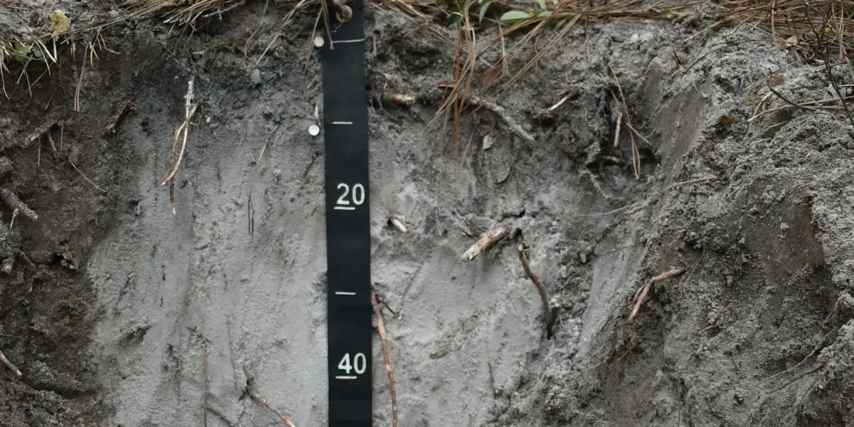
Dans l'ingénierie des réseaux, la Classe de Sol 5 est fréquemment caractérisée comme instable ou meuble, présentant des défis significatifs pour l'intégrité de l'ancrage à long terme. Ces conditions consistent souvent en argiles molles, limons ou sols sableux qui offrent une résistance frictionnelle naturelle minimale. Le risque principal en Classe 5 n'est pas la défaillance immédiate du matériel d'ancrage, mais le fluage graduel et le délitage de la tige d'ancrage sous des charges de tension soutenues au fil du temps. Parce que la matrice du sol elle-même fournit peu de verrouillage mécanique, le fardeau entier de la stabilité repose sur la conception de l'ancrage et sa capacité à répartir la charge sur une plus grande surface.
Nous avons constaté que dans ces environnements meubles, les types d'ancrages standards performe souvent en deçà des attentes sauf si spécifiquement sélectionnés pour une rétention à haute capacité. Pour atténuer les risques de délitage dans le sol de Classe 5, les ingénieurs doivent spécifier des ancrages dotés de plus grandes plaques en hélice ou de mécanismes d'expansion spécifiques capables de consolider le sol environnant pendant l'installation. Il est critique de sélectionner des configurations classées pour les capacités de tenue les plus élevées afin de compenser le manque de densité du sol. De plus, nos données de terrain suggèrent que la profondeur d'installation devient la variable décisive ; enfoncer l'ancrage jusqu'à une strate plus profonde et plus stable est souvent la seule méthode viable pour garantir que le système de haubanage reste sécurisé sous les événements de charge de vent et de glace.
Évaluation de la Capacité Portante de la Classe de Sol 6
La Classe de Sol 6 représente une condition intermédiaire, typiquement constituée de sables de densité moyenne ou d'argiles fermes. Cette classe de sol offre un niveau modéré de capacité portante, fournissant un équilibre entre pénétrabilité et pouvoir de tenue. Contrairement à la nature imprévisible de la Classe 5, les sols de Classe 6 permettent généralement des profondeurs d'installation d'ancrage cohérentes sans nécessiter une force excessive ou des machines lourdes spécialisées. Cependant, “ intermédiaire ” n'implique pas “ sûr ”. La variabilité de la teneur en humidité peut altérer significativement la résistance au cisaillement du sol, signifiant qu'un site qui teste bien dans des conditions sèches peut perdre une capacité portante substantielle après de fortes pluies.
Lors de l'évaluation des sites de Classe 6, effectuez toujours des essais de charge de preuve sur les ancrages installés avant la mise en tension des haubans. Cela confirme que le sol n'a pas été excessivement perturbé pendant l'enfoncement et vérifie que la capacité portante théorique s'aligne avec la performance réelle sur site.
Analyse des Conditions de Classe de Sol 7 à Haute Densité
Les conditions de Haute Densité de Classe de Sol 7, qui peuvent inclure des argiles raides, du duricrust ou des substrats rocailleux, présentent le problème inverse de la Classe 5. Ici, le défi porte moins sur la capacité de tenue que sur la faisabilité d'installation et la contrainte mécanique. La haute densité du sol crée une résistance immense contre la tige d'ancrage lors de l'enfoncement, menant à une montée rapide du couple d'installation. Si la tige d'ancrage ou l'œillet n'est pas fabriquée avec une résistance à la traction et une ductilité supérieures, la friction élevée rencontrée dans le sol de Classe 7 peut déformer physiquement ou cisaillements le matériel avant d'atteindre la profondeur totale.
Dans notre processus de fabrication, nous adressons cela en utilisant des composants en acier chaudement forgeés plutôt que des fontes. Cela garantit que l'œillet et la tige de l'ancrage peuvent résister aux efforts de torsion et axiaux requis pour pénétrer un sol dense sans défaillance fragile. Lorsque l'on travaille en Classe 7, les installateurs doivent être vigilants face au “ refus ” – le point où la résistance du sol dépasse la limite élastique de la tige de battage. Tenter de forcer un ancrage au-delà de ce point peut endommager le point d'attache du hauban. Dans ces scénarios, des ancrages plus petits ou le forage de trous pilotes peut être nécessaire pour atteindre la profondeur de conception tout en préservant l'intégrité structurelle du matériel.
| Paramètre | Spécifications | Unité | Condition |
|---|---|---|---|
| Capacité de fixation | 4,500 to 24,000 | lb | Dependent on soil class and anchor type |
| Driving Resistance | 400 to 2,300 | ft-lbs | Installation requirements vary significantly based on rod diameter and soil resistance conditions. |
| Anchor Types | Helical, Expanding, Cross-plate, No-wrench Screw, Arrowhead | S/O | Selected based on ground conditions |
| Protection contre la corrosion | > 85 | Microns | Hot-Dip Galvanized (ISO 1461 / ASTM A153 Class C) |
| Structural Integrity | Hot-Forged Construction | Enhanced Torsional Strength | Resists bending under load and withstands impact driving forces |
Rassembler les Outils Nécessaires
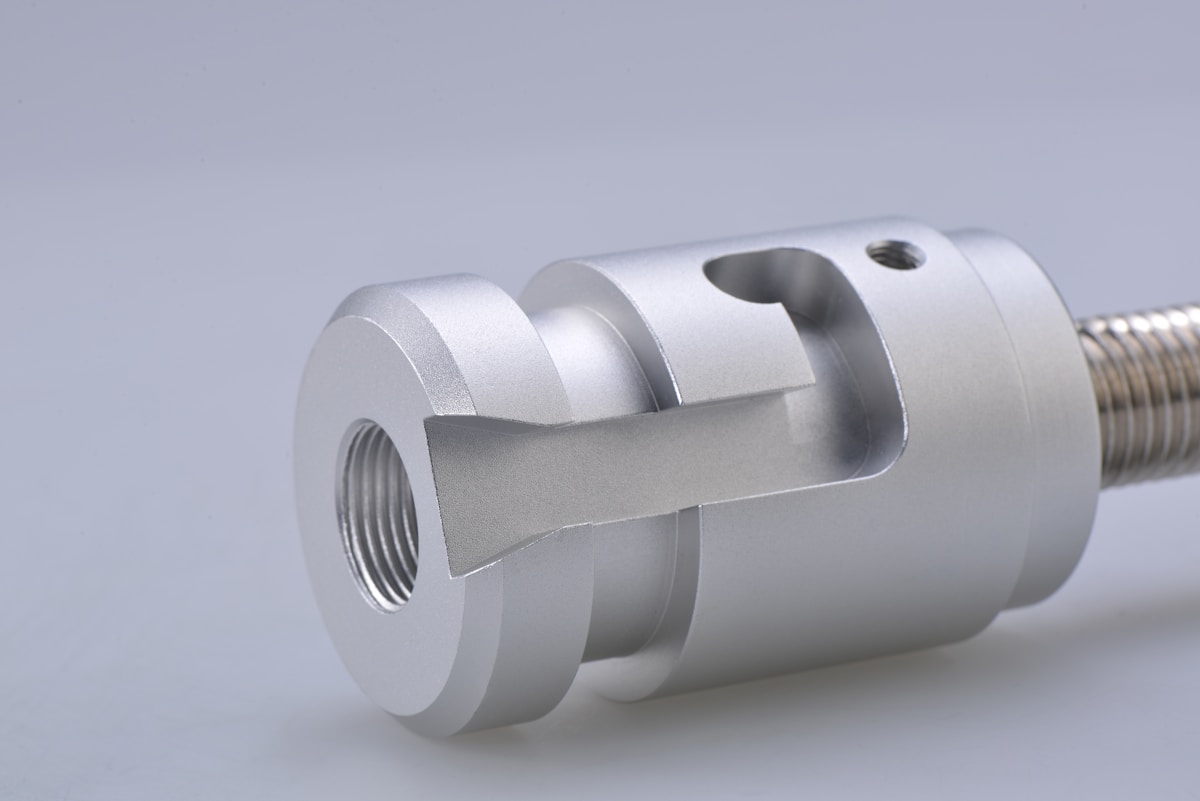
Kinetic energy matching is the primary determinant in selecting drive tools for arrowhead anchors. This technical requirement ensures that sufficient force is applied to overcome Class 7 refusal without compromising the integrity of hot-forged steel components, thereby preventing anchor stalling or structural damage.
Sélection des Outils Manuels d'Enfoncement pour les Fines Tiges
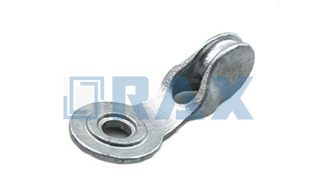
For small diameter anchors and lighter duty applications, manual driving tools remain a cost-effective and portable solution. The primary manual tools include sledgehammers and fence drivers, often referred to as “post drivers.” These tools rely on the operator’s physical force and gravity to drive the anchor to the required depth. However, the efficiency of manual driving depends heavily on the interface between the hammer and the anchor, which is mediated by a drive rod (sometimes called a drive gad).
When using manual methods, it is critical to select a drive rod with the correct shank diameter to fit the anchor’s driving socket. Smaller hammers and gasoline-powered drivers typically utilize a rod measuring 22.2 mm (0.875 in) in diameter. The end of the rod inserted into the anchor requires precise machining; if the clearance is too tight, the anchor may seize on the rod, while excessive clearance leads to inefficient energy transfer. Furthermore, the rod end must be machined so it does not bottom out in the socket, preventing the rod end from flaring or mushrooming inside the anchor—which would make extraction impossible.
Choix des Équipements Hydrauliques pour les Ancrages de Grand Diamètre
When dealing with larger diameter anchors or installing in high-volume environments, manual labor is often insufficient to achieve the necessary depth and holding capacity. Hydraulic and pneumatic impact hammers provide the repetitive, high-force energy required to penetrate dense substrates without operator fatigue. These systems are essential for projects requiring consistent installation depths across multiple anchor points.
The specifications for drive rods change significantly when moving to hydraulic equipment. Most hydraulic and pneumatic hammers require a heavier-duty drive rod to withstand the increased impact forces, typically necessitating diameters of 28.6 mm (1.125 in) or 31.8 mm (1.25 in). These larger rods must be made of high-strength steel to prevent bending during the operation. Additionally, hydraulic setups allow for better control over the driving frequency, enabling the operator to adjust the impact rate based on the ground resistance encountered in real-time.
Appariement de l'Équipement d'Enfoncement aux Niveaux de Densité du Sol
The selection of driving equipment must be dictated by a preliminary assessment of the soil’s resistance. Using equipment that lacks sufficient power for the specific soil density will result in the anchor stalling before reaching the design depth, compromising the holding capacity. Conversely, using excessive force on a small anchor in soft soil can deform the anchor shaft or damage the head mechanism.
- Low Density (Loose Soil): Manual drivers or light hydraulic hammers are usually sufficient. The soil offers little resistance, so the primary goal is control rather than raw force.
- Medium Density (Compacted Soil): A standard hydraulic or pneumatic hammer is generally required. The repetitive impact is necessary to overcome the friction and compression of the soil.
- High Density (Rocky or Hard-Pan): Heavy-duty hydraulic breakers or high-frequency impact hammers are mandatory. In these conditions, the drive rod acts as a critical shock absorber; ensure the rod material is rated for high-impact loads to prevent shearing.

L'Angle de l'Ancrage est-il Correct ?
Impact de l'Écart d'Installation sur l'Intégrité Structurelle
The single most frequent cause of premature anchor failure in utility pole installations is angular deviation from the intended guy wire load vector. Industry engineering standards dictate that an earth anchor must be aligned within 5 degrees of the guy load angle to prevent catastrophic strength loss. When installation deviates beyond this narrow tolerance, the holding capacity of the anchor drops disproportionately, often resulting in sudden structural collapse under heavy wind or ice loads.
La Physique du Désalignement
Anchors are specifically engineered to resist tensile forces pulling directly against their longitudinal axis. When an anchor is installed at an incorrect angle, the pullout force is split into two vectors: one effective axial force and a secondary lateral force. This lateral component creates shear stress across the anchor shaft and the surrounding soil matrix. Soil possesses high compressive strength but very low shear resistance. Consequently, even a minor angular error can cause the soil immediately around the anchor flanges or blades to shear away, stripping the anchor completely from the ground.
- Misalignment Tolerance: Strict adherence to a +/- 5-degree variance relative to the guy wire tension line is required for standard helical and driven anchors.
- Shear Failure: Incorrect angles induce lateral shear forces that exceed the soil’s natural cohesion, leading to immediate ground tearing.
- Capacity Loss: A deviation exceeding 5 degrees can reduce the effective safe working load of the anchor by 20% to 40%, depending on soil density.
Optimisation de la Direction d'Installation pour les Pentes
On uneven terrain, the anchor angle must be determined dynamically based on the relationship between the pull direction and the natural slope. If the guy wire pulls upslope, the anchor should be angled slightly upward to maximize engagement with undisturbed soil layers. Conversely, downslope pulls require the anchor to be oriented more horizontally or slightly downward. Failing to adjust for the ground slope introduces unnecessary bending moments on the anchor rod, further compromising its structural integrity.
Installation precision is the primary determinant of long-term grid reliability. A mathematically correct anchor design cannot compensate for poor angular placement during the driving process.
Enfoncer l'Ancrage en Profondeur Totale
Once the angular orientation is verified, the next critical phase involves ensuring the anchor reaches its designated depth. This step is equally vital, as improper depth can undermine even the most precise installation.
In the utility industry, a common failure point is installing ground anchors at insufficient depths. For utility projects in high-wind zones or areas with unstable topsoil, pulling an anchor short of its target depth compromises the entire guy wire system. Driving the anchor to full depth ensures the structural load is transferred effectively to stable soil layers rather than relying on loose surface dirt.
Éliminer l'Incertitude du “ Point de Réponse ”
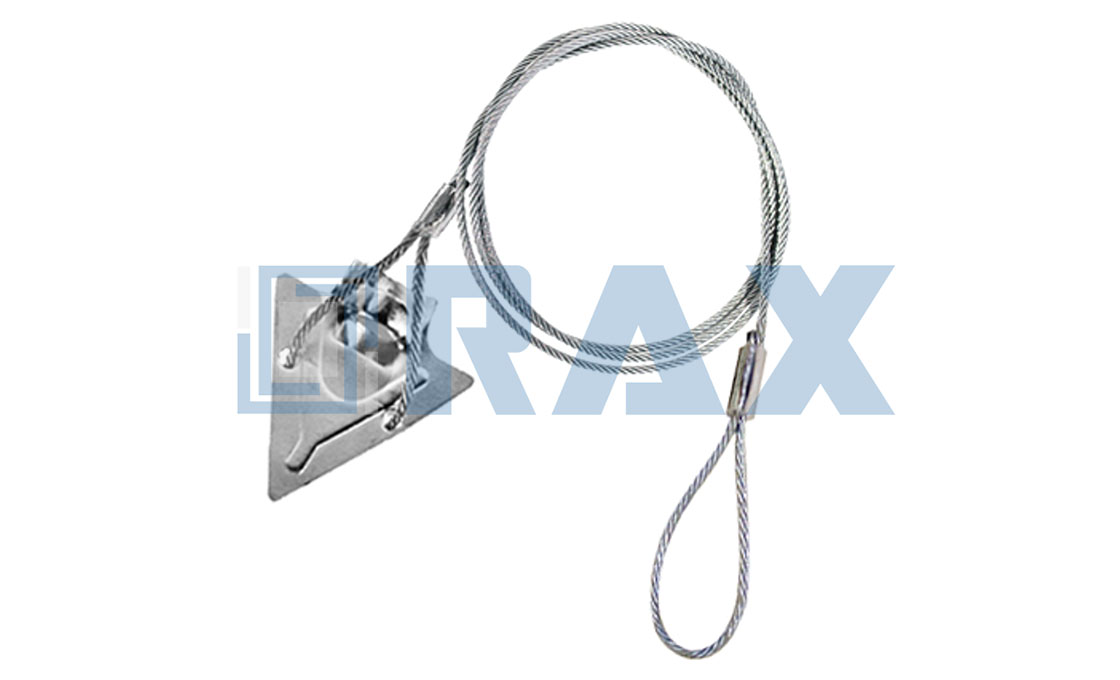
The fundamental risk when driving anchors—such as arrowhead or duckbill designs—is stopping prematurely. If an anchor is not fully seated, the cable will not “key” correctly when tensioned, resulting in minimal holding strength. The standard manual installation procedure involves three precise steps: driving the anchor into the ground using a drive rod and impact tool (sledgehammer, fence driver, or hydraulic hammer), removing the drive rod, and pulling the cable to set the anchor.
During this process, the anchor head must face away from the intended pull direction. As you drive the anchor, you should be able to detect a distinct increase in resistance when the anchor reaches the desired depth. This physical feedback confirms that the anchor has reached the correct positioning to bear the load.
Sélection de la Méthodologie d'Enfoncement Adaptable
The method used to drive the anchor depends entirely on the anchor’s size and the local soil density. For smaller anchors, such as a 50.8 mm (2-inch) diameter unit, field crews typically utilize a standard drive rod and a sledgehammer. In softer soils, similar to those used for driving steel fenceposts, manual driving devices are highly effective.
However, for larger diameter anchors or installations requiring significant penetration into dense clay or rocky strata, manual methods are often impractical. In these scenarios, electric or pneumatic impact hammers are required to drive the anchor at the desired angle until it cannot be driven further. No concrete or grout is required for these mechanical systems; their holding capacity relies strictly on proper placement within the earth.
Applications Convenables et Contraintes des Sols
- Tower and Antenna Mounting: Critical for ensuring base stability where soil conditions fluctuate.
- Erosion Control Systems: Anchors must reach deep enough to avoid being washed out during heavy rainfall events.
- Portable Shelter Guying: Properly keyed anchors prevent wind-blown collapse of temporary structures.
Appliquer le couple et la tension corrects
Vérification de l'Intégrité de l'Ancrage par Essai de Charge de Preuve
Proof load tensioning serves as the definitive verification of anchor engagement and locking mechanism activation. For driven arrowhead anchors, this process requires applying a specific upward tension to rotate the head into a perpendicular locking position. Industry standards dictate applying a proof load—typically 50% to 100% of the anchor’s rated Safe Working Load (SWL)—to confirm the anchor has toggled correctly without excessive displacement. Installers must account for the physical behavior of the anchor rod during this phase, as the steel rod or cable will inevitably shorten or move upward as the anchor head rotates and soil compresses; failing to compensate for this “set” movement can result in a false reading. If the anchor pulls out easily or fails to reach the designated tension resistance, the locking mechanism has not engaged, rendering the installation void regardless of drive depth.
Installers must account for the physical behavior of the anchor rod during this phase. During the initial tensioning, the steel rod or cable will inevitably shorten or move upward as the anchor head rotates and soil compresses. Failing to compensate for this “set” movement can result in a false tension reading. To ensure the anchor is secure, the tension must be held at the proof load level for a specific duration (often 1 to 3 minutes) to check for creep, ensuring the holding power is derived from soil mechanic locking rather than friction.
Gestion du Couple pour les Pièces de Terminaison
While the anchor relies on tension, the connection point—guy clamps, pole bands, and eyenuts—relies strictly on torque. A common failure mode in B2B utility projects is the “false torque” caused by high-friction galvanized coatings. When hardware features a heavy hot-dip galvanized coating (e.g., exceeding 85 microns), the nut may bind against the threads before achieving true clamping force. Insiders know that the “click” of a torque wrench does not always guarantee optimal preload if the friction factor is not calculated.
- Initial snug-tight: First bring all connected components into firm contact to ensure uniform load distribution.
- Pattern tightening: On multi-bolt clamps (such as guy clamps or pole bands), follow a star or cross-pattern sequence to prevent uneven pressure that could distort the galvanized layer or damage the conductor.
- Final verification: Re-check torque values after the anchor has been fully tensioned and loaded, as settling can cause initial bolt tension to relax.
Diagnostic des Problèmes de Résistance
The relationship between input force and resistance provides immediate diagnostic data. When tensioning an anchor, if the required proof load is met with virtually no resistance, the anchor is likely installed in loose soil or voids and has not toggled. Conversely, if resistance spikes abruptly and exceeds the proof load limit before the anchor sets, it may indicate obstruction (like a rock) preventing the head from rotating. In this scenario, continued application of force risks rod failure. The correct procedure involves monitoring the load curve; a successful set is usually indicated by a distinct “peak” in tension followed by a slight drop or plateau as the anchor rotates 90 degrees into the locked position.

Confirmation que l'Ancrage est Bien Fixé
The verification phase is the definitive checkpoint where installation transitions from execution to assurance. Visual estimates of soil density or driving torque are insufficient guarantees of long-term stability; a physical verification of the anchor’s holding power is required. For utility contractors and project managers, the primary pain point is mitigating the risk of “creep”—the gradual movement of an anchor under load that eventually leads to pole failure. To eliminate this risk, the confirmation process must rely on direct mechanical evidence rather than assumptions.
Executive Insight: Visual estimates of driving torque are insufficient for verifying long-term anchor stability. Since Arrowhead anchors are impact-driven, torque is irrelevant to their holding capacity. A “soft” bottom in the driving hole can cause an anchor to set at the wrong depth, reducing its ultimate strength by up to 50%. Always verify final position via visual audit and perform a proof load test to mitigate creep risk.
Inspection Visuelle de l'Alignement et de la Profondeur de la Tige
Before applying any significant tension, a visual audit of the anchor rod is necessary to confirm proper engagement of the locking mechanism. The rod must exit the ground at the precise angle required for the guy wire assembly, typically matching the pole’s guying angle. If the rod emerges at a divergent angle, the internal anchor head may not have toggled correctly, or it may have encountered a subsurface obstruction.
- Rod Straightness: Ensure the anchor rod is not bent. A bent rod indicates the anchor struck a rock or root, preventing the head from reaching its intended depth and locking position.
- Depth Verification: Check that the rod is driven to the full specified depth. Stopping short—even by a few inches—can place the anchor in a shallow, unstable soil layer, drastically reducing load capacity.
- Coating Integrity: Inspect the section of the rod near the ground line. While minor abrasions are acceptable, deep gouges exposing bare steel can compromise corrosion resistance over the asset’s lifespan.
Réalisation de l'Essai de Charge de Preuve
The most reliable method to confirm an anchor is secure is to subject it to a proof load test. This involves applying a tension force via a dynamometer or come-along that exceeds the anticipated working load but remains below the anchor’s ultimate yield strength. This test “pre-loads” the system, settling the anchor into the soil and confirming that it will not slip under operational forces.
For arrowhead and no-wrench anchors, the proof load also verifies that the toggle mechanism has fully deployed and engaged the soil. If the anchor pulls out or stretches excessively during this test, it must be removed and re-installed in a new location. Extrapolating data from a single test site to other anchors is not recommended due to soil heterogeneity; each critical anchor should be individually verified.
Connexion Finale et Transfert de Charge
Once the anchor has passed the proof load test, the final step is securing the guy wire assembly. This involves attaching the thimble eye or guy grip to the anchor rod and tensioning the guy wire to the engineer’s specified sag or tension. It is crucial to ensure that the rod’s eye is oriented correctly to minimize side-loading on the clevis or bolt.
After the full guy wire tension is applied, perform a final visual check. The anchor rod should remain rigid with no visible vibration or movement. Only after this comprehensive confirmation—combining depth checks, proof loading, and final visual inspection—should the anchor be considered secure for service.
Calcul de la Charge de Travail Sécuritaire
Application des Coefficients de Sécurité pour les Types de Sol Variables
Treating soil as a constant value in your load calculations is a rookie mistake that leads to catastrophic failure. The ground is dynamic, and its holding potential varies drastically based on moisture content, compaction, and stratification. To calculate a realistic Safe Working Load (SWL), you cannot rely solely on the ultimate holding capacity derived from laboratory tests in ideal conditions. Instead, you must apply a soil-specific factor of safety to account for these real-world inconsistencies.
For instance, while an anchor might exhibit exceptional results in dense clay, the same anchor installed in loose sandy loam will experience a significant drop in holding power. Industry best practices dictate applying a safety factor ranging from 2:1 to 4:1 over the ultimate holding capacity, depending on the criticality of the infrastructure and the variability of the soil classification. This derating ensures that if the soil settles, saturates, or shifts, the anchor system maintains its integrity without approaching the yield point. In our experience working with global utility markets, underestimating the impact of soil variance is the primary cause of anchor creep and eventual pull-out failure.
Calcul des Limites de Charge Basées sur la Résistance de la Tige
The anchor rod is the backbone of the system, and its tensile and shear strength defines the upper ceiling of your load calculation. Regardless of how stable the soil is, if the rod yields, the system fails. When calculating load limits, you must verify that the Ultimate Breaking Strength (UBS) of the rod significantly exceeds the SWL of the soil attachment. This requires looking beyond basic steel grades and examining the manufacturing process.
We prioritize hot-forged steel components over castings because the forging process aligns the grain structure of the metal, resulting in superior fatigue resistance and impact toughness. Under dynamic loads—such as wind-induced vibrations on utility poles—cast materials are prone to brittle fracture, whereas our forged rods maintain structural integrity, allowing you to calculate load limits with higher confidence.
Furthermore, the calculation must account for potential bending moments. If the guy wire attachment point induces a lateral force, the rod is subjected to both tension and bending. Your load limit calculation should reduce the rated tensile capacity to accommodate this combined stress vector. Our in-house testing frequently reveals that while a rod might handle a straight pull efficiently, a 15-degree deviation due to installation error can reduce its effective load capacity by over 30%.
Détermination des Charges de Travail Sécuritaires pour les Applications de Distribution
For utility projects, the final SWL is not just a number; it is a legal and engineering liability threshold. The standard formula for determining SWL in high-stakes environments is the Ultimate Holding Capacity (UHC) divided by the Safety Factor (SF). However, utility applications introduce dynamic variables like wind load, ice accumulation, and thermal expansion that static calculations often miss. Therefore, the SWL must be the minimum value between the soil’s capacity and the rod’s strength, further reduced by the installation quality factor.
- Dynamic Load Verification: Ensure the SWL accounts for transient loads, not just the static weight of the pole and hardware.
- Standard Compliance: Load calculations must align with relevant standards (such as CEI 120) which define specific gauge testing protocols to verify that hardware can withstand the calculated forces.
- Corrosion Derating: Long-term SWL must consider material loss over the asset lifecycle. We ensure a coating thickness exceeding 85 microns to minimize the reduction of the rod’s cross-sectional area over time, preserving the original SWL calculation.
We conduct rigorous load testing in our facility to verify that the theoretical calculations match real-world performance. By subjecting our anchors to loads exceeding their rated capacity, we validate that the SWL provided to engineers includes a necessary buffer for the unforeseen stresses inherent in power transmission networks.
| Calculation Variable | Technical Specification | Influencing Factor | Performance Outcome |
|---|---|---|---|
| Ultimate Holding Capacity | 4,500 – 24,000 lbs | Soil Classification (Class 7 to Class 5) | Determines maximum load limit; capacity increases in dense soils (Class 7) compared to loose soils (Class 5). |
| Driving Resistance | 400 – 2,300 ft-lbs (Equivalent) | Rod Diameter & Soil Density | Soil density and rod diameter dictate the driving resistance required for proper anchor set. Adequate driving force ensures the anchor locks into the soil profile. The listed figures represent screw anchor torque equivalents rather than direct impact resistance values. |
| Load Vector Angle | 45° Standard Guy Lead | Attachment Height & Horizontal Distance | Angles closer to parallel ground maximize resistance; vertical pull significantly reduces holding power. |
| Structural Strength | Hot-Forged Steel | Manufacturing Process (vs Casting) | Provides superior grain structure ensuring high-breaking load integrity and fatigue resistance. |
| Corrosion Allowance | Revêtement >85 microns (ISO 1461) | Environmental Exposure | Ensures long-term material stability; critical for maintaining SWL over the asset lifecycle. |
Assurer la Sécurité et la Conformité
Compliance is non-negotiable in utility infrastructure. Safety relies on verifying material grades, coating thickness, and dimensional tolerances against strict ISO and ASTM standards before installation begins.
Vérification de la Conformité aux Normes de Galvanisation ISO 1461
In the utility sector, “galvanized” is a vague term that can mask significant quality variances. For pole line hardware and earth anchors, the benchmark for corrosion protection is the ISO 1461 standard, alongside ASTM A153 Class C. These specifications dictate not just the presence of a zinc coating, but its adherence, uniformity, and density. Electroplating or shallow dipping may look adequate initially but often fails prematurely under the stress of ground contact and variable soil pH.
Buyers must demand a specific mean coating thickness in their technical specifications. While industry minimums exist, they often leave little margin for error in aggressive environments. We strictly adhere to a mean coating thickness exceeding 85 microns in our hot-dip galvanizing process. This thickness, verified by SGS testing, provides a strong sacrificial layer that significantly extends the service life of the hardware, preventing rust from compromising the structural integrity of the anchor system.
Do not accept “minimum” coating thickness as a quality metric. A standard 60-micron coating might pass basic checks but will corrode faster in salty or high-humidity regions. Always specify a higher mean value (e.g., 85 microns) for critical infrastructure.
Garantie des Tolérances d'Installation pour la Durabilité à Long Terme
Dimensional accuracy is not merely about fit; it is a safety determinant. Poorly toleranced components create uneven load distribution, leading to stress concentrations at connection points. In the case of cross arms and bracket assemblies, even a deviation of a few millimeters can misalign the guy wire or conductor, introducing lateral forces that the pole was not designed to withstand. This misalignment accelerates fatigue failure at the anchor point and the pole attachment.
To mitigate these risks, manufacturing must utilize automated production systems that eliminate human error. Our facility utilizes automated and semi-automatic machinery to enforce a strict 1mm tolerance on critical dimensions like cross arm lengths and hole spacing. This precision ensures that when the components arrive on-site, they fit together smoothly without the need for field modifications that could void warranties or weaken the structure.
Confirmation des Nuances de Matériau pour la Résistance à la Corrosion
The base metal composition determines the hardware’s ability to withstand mechanical stress before the galvanizing even comes into play. There is a critical distinction in the industry between components produced via traditional casting and those manufactured through hot-forging. Cast parts often contain micro-voids and impurities that act as initiation points for corrosion and cracks under heavy loads. Hot-forged steel, by contrast, refines the grain structure of the metal, resulting in superior tensile strength and impact resistance.
We prioritize hot-forging for our high-load hardware to ensure structural integrity exceeds the requirements of the application. Every batch undergoes rigorous testing, including load testing and gauge testing per IEC 120 standards, conducted in-house by our dedicated QC team. This process confirms that the material grade meets the necessary yield strength, ensuring the anchor will not deform or snap under maximum tension conditions. Verifying mill certificates and test reports is a mandatory step for any procurement team to guarantee they are receiving engineered structural steel rather than generic ironwork.
- Mill Test Certificates (MTC): Always request MTCs to verify the chemical and mechanical properties of the steel used.
- Forging vs. Casting: Prioritize hot-forged components for high-stress guy wire and anchor applications to avoid brittle fracture.
- In-House Verification: Look for manufacturers who perform internal IEC 120 load testing, rather than relying solely on third-party sampling.
Conclusion
Successful installation relies on matching hydraulic equipment to anchor diameter and verifying soil class before driving. Proper installation of arrowhead bullet anchors depends on soil density and correct drive depth, necessitating adjustments for conditions ranging from Class 7 to loose soil. Because these anchors are impact-driven, avoiding over-stressing the galvanization is essential to maintain structural integrity. You must match your hydraulic equipment to the anchor diameter for consistent results. Our engineering team reviews these variables daily at our ISO-certified facility, where we prioritize hot-forging quality.
- Confirm ASTM A153 coating integrity on all rods before shipment
- Calculate safe working loads based on actual soil bearing capacity, not estimates
- Use our engineering support for complex load calculations instead of guessing
Questions fréquemment posées
Comment fonctionnent les ancrages Arrowhead ?
Arrowhead anchors function by penetrating the soil through rotation, allowing the helical blades to screw into the ground. As they advance, the soil compresses against the blades, creating significant friction and interlocking forces. This mechanical engagement transfers the tensile load from the guy wire directly into the stable earth strata, providing secure anchorage for overhead line structures.
Quelles sont les applications courantes des ancrages Arrowhead ?
These anchors are primarily used for guy-wire stabilization of utility poles, transmission towers, and communication masts. They are also essential in solar farm mounting systems, temporary structure bracing, and retaining wall tie-backs. Their versatility makes them suitable for both permanent infrastructure and temporary construction projects requiring reliable ground anchoring.
Ancrage Arrowhead vs ancrage Duckbill : lequel est meilleur ?
The choice depends on soil conditions and installation constraints. Arrowhead anchors offer higher holding capacity in dense or rocky soils due to their continuous helix design, while duckbill anchors are often preferred for easier installation in softer, sandy soils. Engineers typically select arrowheads for critical high-load applications where maximum pull-out resistance is required.
Quels essais normalisés s'appliquent aux ancrages ?
Anchors undergo rigorous load and gauge testing per IEC 120 standards to verify their mechanical properties. In-house testing facilities conduct these evaluations to ensure consistency across all production batches. Additionally, third-party verification by SGS confirms that all processes and products meet global safety and quality requirements for utility applications.
Les conceptions personnalisées peuvent-elles être accommodées ?
Yes, manufacturers often provide OEM/ODM services to transform specific drawings or concepts into finished products. Custom mold development allows for tailored solutions that meet unique regional tender requirements or specialized engineering needs. This flexibility ensures that clients receive hardware precisely sized and configured for their specific project parameters.