
Imagine o poste em que uma traverse completa jamais se encaixa: os condutores saem apenas para um lado, e todo o braço em balanço depende do seu hardware. A instalação correta da escora do braço de beco impede que esse braço montado lateralmente gire, ceda ou se desalinhe sob a carga dos condutores. Bem ajustada, a escora funciona em silêncio por uma década; mal ajustada, torna-se o ponto onde a equipe sempre precisa voltar.
Do lado do fabricante deste hardware, duas coisas importam: precisão no ajuste e qualidade do acabamento. A RaxPower fabrica hardware para linhas de poste galvanizado por imersão a quente desde 2003, e os mais de 170 profissionais por trás da linha trabalham sob gestão da qualidade ISO 9001, com galvanização conforme ISO 1461. Este guia percorre a sequência de montagem da forma como um mestre de obras explicaria: onde a escora se posiciona, qual fixador entra primeiro e o que verificar antes de descer.
Onde a Escora se Posiciona no Braço Montado Lateralmente
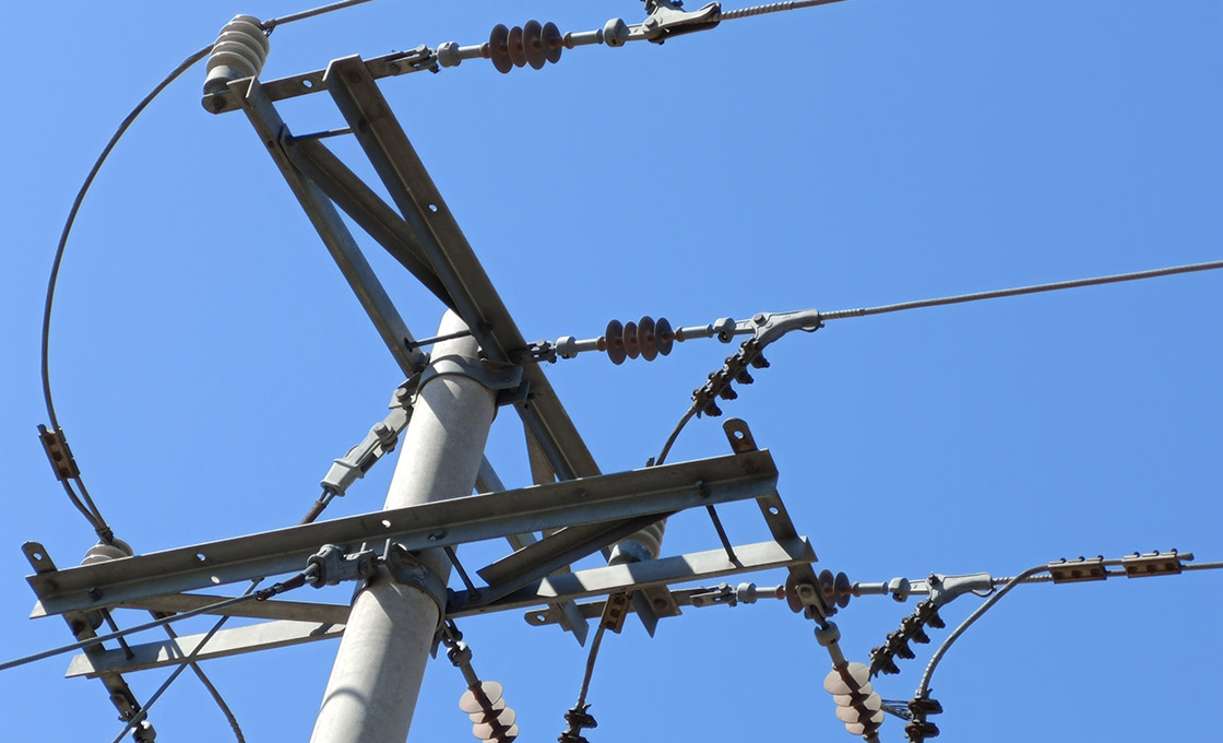
Um braço montado lateralmente altera o caminho da carga. Em uma estrutura de tangência normal, a traverse de madeira fica centralizada no poste e suas escoras planas funcionam como par. Um braço de beco é fixado a uma face do poste e se estende em balanço, suportando condutores onde uma traverse completa não consegue chegar. É por isso que becos e vãos apertados de passagem utilizam esse recurso.
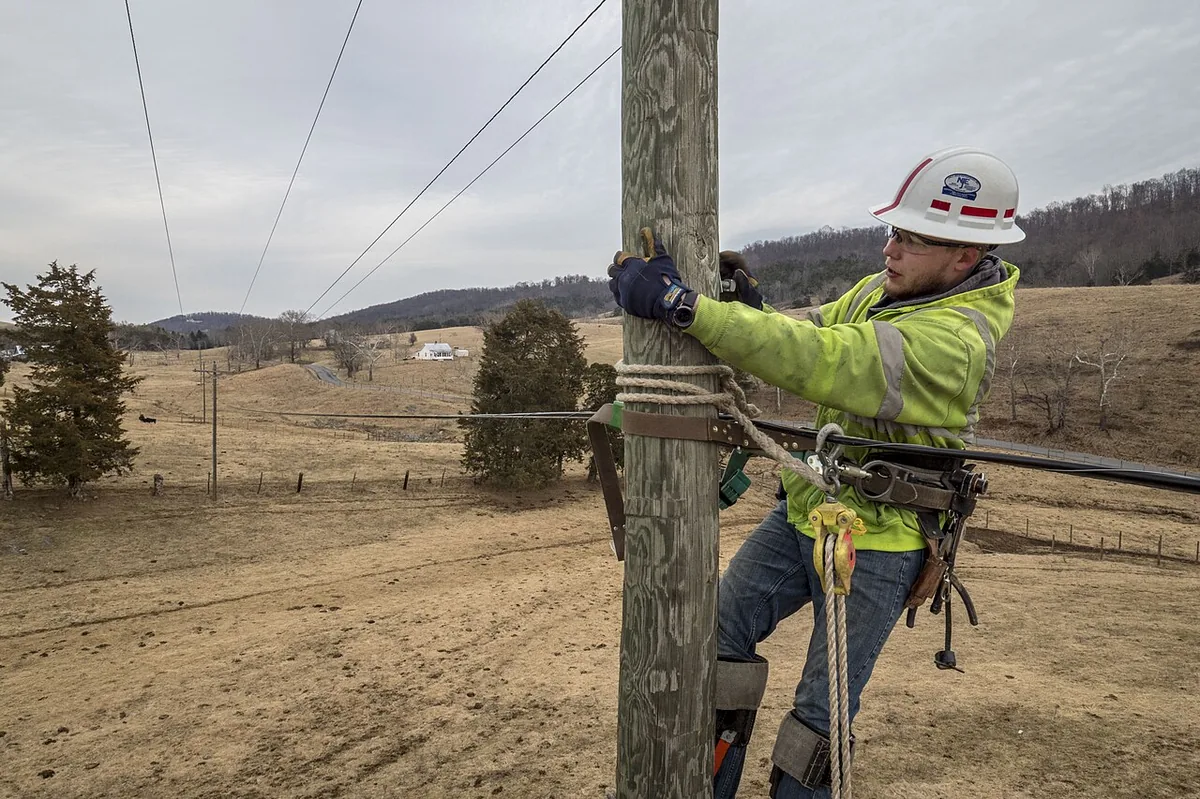
A escora é o contrapeso desse balanço. Ela vai do lado do braço até o poste abaixo, mantendo a geometria em ângulo de 45 graus. A maioria dos projetos adiciona um degrau soldado para eletricista, de modo que a mesma escora também funcione como posição de trabalho no poste.
Por que simplesmente usar um braço mais grosso? Porque o balanço multiplica cada libra de carga do condutor em um momento torsional na face do poste, e a madeira sozinha não consegue combater essa alavanca. A escora converte a torção em uma linha de compressão reta, que o poste suporta bem.
Catálogo de braços de beco da MacLean é uma referência comum para essas escoras, e resume o projeto em uma linha. A escora é de aço galvanizado por imersão a quente, fixada ao lado do braço e presa ao poste em 45 graus.
“Fixar ao braço de beco usando parafuso de máquina e fixar ao poste usando (2) parafusos de fixação de 1/2 pol. através de furos de 9/16 pol.” — Especificação de escora de braço de beco, MacLean Network Solutions
| Modelo de referência | Comprimento | Furo de montagem | Perfil angular |
|---|---|---|---|
| J1522 | 5 pés | 9/16 pol. | 1-3/4 × 1-3/4 × 3/16 pol. |
| J1525 | 7 ps | 11/16 pol. | 1-3/4 × 1-3/4 × 3/16 pol. |
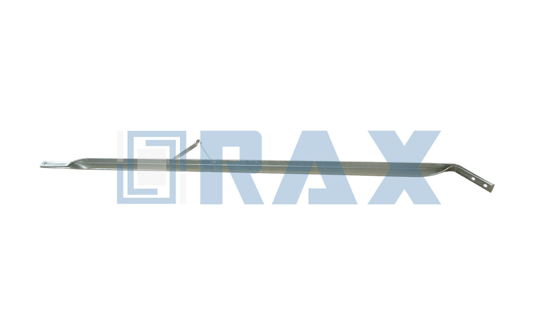
O tamanho do furo é o detalhe a confirmar antes de qualquer coisa sair do caminhão. Uma escora de 5 pés requer furos de 9/16 pol. e uma escora de 7 pés requer furos de 11/16 pol., de modo que o hardware do caminhão deve corresponder ao desenho técnico.
Antes de Subir: Preparação e Checklist de Hardware
Quando o cronograma prevê a substituição de um braço lateral em um beco, faça o planejamento no chão. A instalação da escora do braço de beco é decidida antes que alguém saia do nível do solo: disponha o hardware e conte as peças. Uma escora, um parafuso de máquina com porca e arruelas, e dois parafusos de fixação de 1/2 pol. com comprimento suficiente para engajamento total da rosca no poste.
A lista de ferramentas é pequena o bastante para acompanhar no cinto de escalada.
- Chave ou soquete compatível com a porca do parafuso de máquina, além de chave de realinhar furos para alinhar os furos.
- Furadeira com broca para furo guia conforme a norma da concessionária para parafusos de fixação de 1/2 pol.
- Martelo para assentar arruelas e nível para verificar o alinhamento do braço.
- Trena para confirmar o comprimento da escora e o espaçamento dos furos contra o desenho técnico.
Verifique o próprio braço antes de aplicar qualquer hardware. Um braço trincado ou fissurado pelo intemperismo falhará independentemente de quão bem a escora se encaixe. A mesma lógica se aplica à linha de travessas elétricas, uma vez que o escoramento só funciona quando o elemento que suporta está em boas condições.
Parafuse a Escora ao Braço Primeiro
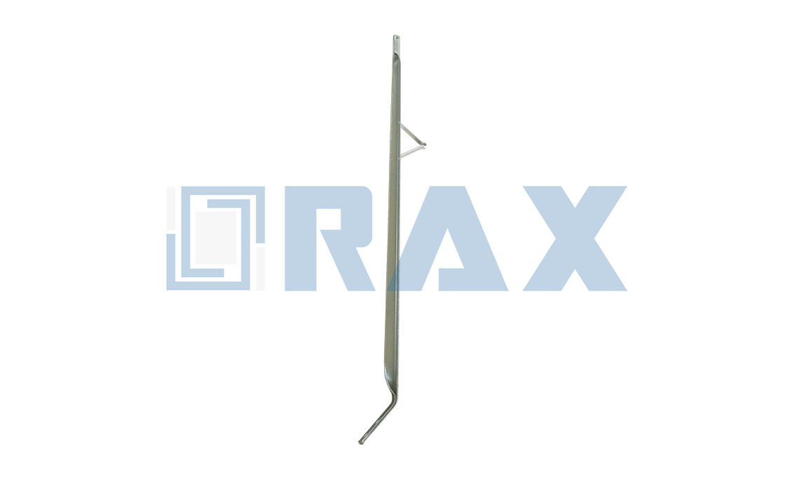
A sequência importa mais que a força aqui. Parafuse a escora ao braço enquanto ambas as peças ainda estão em suas mãos, de modo que o parafuso de máquina possa ser iniciado alinhado e a escora fique folgada o bastante para se ajustar.
A conexão do lado do braço é um único parafuso de máquina passando pelo lado do braço e pelo furo correspondente na escora. Uma arruela sob a cabeça e a porca distribuem a carga de aperto para que o parafuso não esmague as fibras de madeira ao assumir a tensão.
Hole alignment decides how cleanly this goes together. Start the bolt through the brace hole first, tap the shank with a hammer until it marks the arm, then drill or drift the arm hole directly off the mark. A bolt started crooked wallows its hole over time and the connection works loose in service.
Some specifications put a larger 5/8-inch bolt at this position, so read the brace drawing rather than assuming one size. What stays constant is the order: arm first, pole second, because the brace must hang free to find its angle.
Defina o Ângulo e Fixe a Escora ao Poste
With the brace swinging on its arm bolt, the pole connection becomes a geometry task. Swing the brace until it reads 45 degrees to the pole, then mark both lag screw positions through the steel.
Powertelcom’s engineering guide calls 45 degrees the most preferred angle of alignment between the alley arm and the pole, and the physics agree. At 45 degrees the brace resists both the downward sag of the cantilevered arm and the pull along the line.
Drill lead holes for the two 1/2-inch lag screws where the wood calls for them. Lead holes are commonly drilled in harder species, and practice varies by wood and utility standard.
Lag length is the quiet variable. The screw must pass through the brace and the steel-to-wood gap, then bury enough thread in the pole that the shear plane sits in the wood, not at the interface. Hold a candidate lag against the assembled brace and check that purchase before committing.
- Hold the brace at 45 degrees and mark both lag holes through the steel.
- Drill lead holes where the standard requires them, square to the pole face.
- Start both 1/2-inch lag screws by hand so the threads catch true.
- Drive or wrench each lag until the washer seats flat on the steel.
- Confirm the lineman step faces the climbing side before final tightening.
Two lag screws, not one, is what makes this fitting work. The pair stops the brace rotating around a single fastener, and the published specifications are explicit that the pole side gets two.
Justapor vs. Apertar: Prática de Fixação que Permanece
Treat the connection the way you treat a car wheel: snug in stages and re-check later. Bring the machine bolt and both lags to snug first, confirm the 45-degree geometry has not drifted, then take each fastener to final tightness.
How tight is final? Tight to the manufacturer’s specification. No published torque figure exists for alley arm brace installation, and inventing one invites crushed wood at the arm or stripped lag threads in the pole.
In our experience, the crews with the fewest callback failures are the ones who stop at snug, look at the geometry, and only then wrench.
Verificações de Alinhamento Antes de Deixar o Chão
Before the ladder moves, run four checks at the pole. They take two minutes, and together they turn alley arm brace installation into a routine rather than a judgment call.
- Level: the arm reads level across its length with the brace tensioned.
- Angle: the brace still reads 45 degrees after final tightening.
- Engagement: both lag washers sit flat on the steel with threads fully engaged.
- Line: conductors leave the arm spools without sideways pull on the structure.
One check belongs on the ground. Walk back until the whole structure is in view and sight the arm against the pole line. A side arm that looks true at the pole can read a few degrees off from fifty feet.
Erros Comuns de Montagem em Construção com Braço Lateral
Most failures trace back to a handful of repeat errors. Each one is avoidable with the checklist above.
- Substituting a flat crossarm brace. Flat braces are a different family: 7/16-inch holes for 3/8-inch crossarm bolts, no lineman step, and the wrong geometry for a cantilevered side arm.
- Driving lags without lead holes in dense wood. The split starts below the surface and shows up as a backed-out screw a season later.
- Reversing the sequence. Lag the pole first and the brace can no longer swing to 45 degrees at the arm; the crew then forces the geometry and fights the hardware.
- Overtightening the arm bolt. Crushed fibers mean lost clamp load over time, which is why the manufacturer’s specification governs rather than arm strength.
- Ignoring step orientation. A welded lineman step that faces away from the climbing side gives nothing back at the next visit.
- Reusing a bent brace from the truck bed. The factory-set angle is the part; once bent, the brace will not repeat its 45-degree geometry.
Every one of these mistakes shows up in the finished geometry. The arm sags, the brace hums in the wind, or the step faces the wrong way, and a ground-level check would have caught all three.
Ritmo de Inspeção Pós-Instalação para Escoras de Braço de Beco
When the crew has left the alley, the inspection rhythm takes over. A check right after energization, then again during routine pole patrols, keeps the fitting honest for its service life.
- Lag screws have not backed out and washers remain flat on the steel.
- The arm bolt keeps tension and the wood shows no new crushing.
- Galvanizing stays intact at the bolt holes with no creep of white rust.
- The 45-degree angle has survived wind and conductor movement.
Frequency depends on environment more than on the hardware itself. Coastal air, de-icing salt, or industrial fallout argue for shorter patrol cycles, while dry inland lines can run the standard schedule. What matters is that the same eyes see the same fitting each time, because drift is gradual and easy to miss between long gaps.
Any lag that backs out twice has stripped threads in the pole. The fix is a filled and redrilled position or a relocated lag, not another turn of the wrench. Braces that arrive bent from storage should be replaced rather than straightened, because the factory-set angle is what makes the geometry repeatable.
Perguntas Frequentes
Em qual ângulo a escora do braço de beco deve se posicionar?
Instale o suporte em 45 graus entre o braço montado lateralmente e o poste. Fabricantes como MacLean listam 45 graus como ângulo padrão de montagem, e é o primeiro valor que os serviços públicos verificam durante a inspeção.
O que fixa a escora ao poste?
Two 1/2-inch lag screws, installed through the 9/16-inch holes in the brace. Seven-foot models use an 11/16-inch hole, so match the hardware to the hole size on the brace you are hanging.
Qual parafuso fixa a escora ao braço?
A machine bolt through the side of the arm, paired with the matching hole in the brace. A washer at the head and nut spreads the load instead of digging into the wood.
Os parafusos de fixação precisam de furo guia no poste?
It depends on the pole wood. Lead holes are commonly drilled in harder species, and practice varies by wood and utility standard. Follow the governing construction standard before driving lags.
Com que força o hardware da escora do braço de beco deve ser apertado?
Snug the connection, confirm the 45-degree geometry, then tighten to the manufacturer’s specification. No universal torque figure is published for alley arm brace installation, so the specification and the utility standard govern.
Escora de Braço de Beco: Principais Pontos em Visão Geral
- Mounting angle: 45 degrees between the brace and the side-mounted arm’s pole.
- Arm connection: one machine bolt through the side of the arm, washer-protected.
- Pole connection: two 1/2-inch lag screws through 9/16-inch holes; 7-foot braces use 11/16-inch holes.
- Typical section: 1-3/4 × 1-3/4 × 3/16 inch hot-dip galvanized steel angle.
- Reference lengths: 5 ft and 7 ft (MacLean J1522 / J1525 sizes).
- Torque: no published universal figure; tighten to the manufacturer’s specification.
Confiança no Poste Vem da Sequência
An alley arm brace rewards the same discipline as any pole top work. Know where the part sits, follow the arm-first order, respect the 45-degree angle, and verify the geometry before leaving. RaxPower has built hot-dip galvanized pole line hardware since 2003, and the fittings that last are the ones installed to specification rather than to habit.