
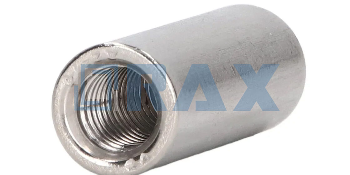
La défaillance structurelle dans les ancrages en sols profonds provient rarement de la rupture de la tige. Elle survient généralement lorsque des tolérances laxistes permettent des micro-déplacements qui transforment une connexion mécanique sécurisée en un risque de fatigue. Un seul raccord de tige d'ancrage doit supporter intégralement les charges de traction sans glissement, ce qui signifie que la géométrie interne du filet est bien plus critique que le boîtier externe.
Notre site de fabrication produit des raccords avec des charges de travail sûres allant jusqu'à 38 000 livres et un coefficient de sécurité strict de 2:1, en s'appuyant sur ASTM A563 Grade C et un taraudage de précision pour prévenir l'écart de pas. Cet article explique comment vérifier la longueur d'engagement des filets et contrôler l'empilement dimensionnel lors de l'assemblage.
Vous apprendrez à utiliser des jauges de contrôle passe/non-passe pour la vérification du diamètre de pas et à ajuster pour l'épaisseur du revêtement afin d'assurer un engagement des filets constant. L'objectif est d'éliminer les variables cachées qui compromettent la disponibilité des réseaux et entraînent une regalvanisation.
Repérer les risques liés à l'empilement des tolérances de filet
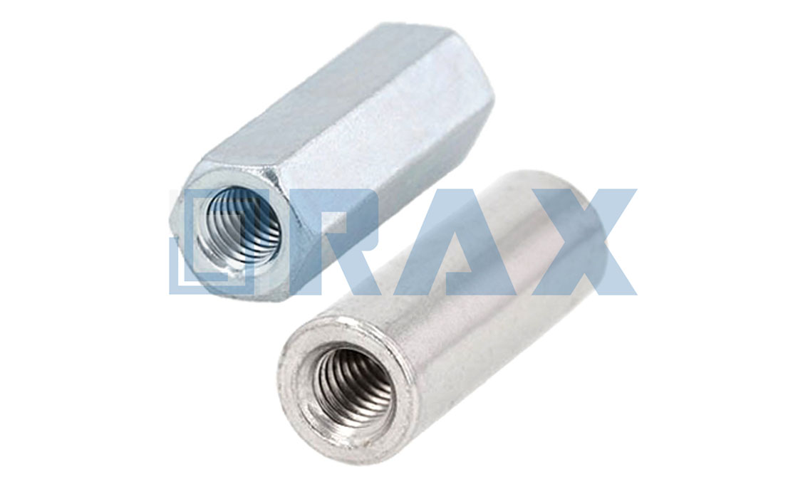
Cumulative pitch deviations in tige d'ancrage couplers compromise tensile integrity and cause erection delays. We adhere to strict dimensional accuracy to ensure universal compatibility with standard drive tools.
In high-load pole line infrastructure, the assembly of continuous anchor rod runs is highly sensitive to the geometric tolerances of coupler threads. A coupler serves as the critical interface between two rods, translating axial tension into mechanical friction and thread engagement. When the manufacturing tolerances for thread pitch or diameter are not held to a precise standard, these micro-variances do not remain isolated; they compound as you move down the string of couplers.
Impact de l'écart cumulatif du pas sur l'assemblage
Thread pitch deviation refers to minor inaccuracies in the distance between adjacent threads. In a single connection, a slight pitch error might be masked by the elasticity of the steel. However, in long utility pole runs where multiple couplers are connected end-to-end, these errors accumulate. This “stack-up” effect creates significant misalignment at the final joint, making it impossible for the rods to seat properly under load.
This misalignment fundamentally compromises the tensile integrity of the structure. Instead of a straight line of force transfer, the rod system experiences induced bending moments. For field crews, this translates directly into severe erection delays, as workers struggle to align the rods manually. In worst-case scenarios, forcing misaligned couplers together creates high-stress concentration points that can lead to premature structural failure under wind or ice loads.
Empilement dimensionnel dans les chaînes multi-raccords
To mitigate the risks of dimensional stack-up, the manufacturing process must guarantee extreme consistency across every single unit produced. Generic off-the-shelf hardware often relies on loose tolerance bands that are acceptable for light-duty applications but dangerous for power transmission grids. When the inner diameter or the external dimensions of the coupler housing vary from batch to batch, the alignment with standard drive tools becomes unpredictable.
Our approach focuses on eliminating this variability before the product leaves the factory. By utilizing automated le forgeage à chaud technology, we maintain a strict tolerance that ensures every triple-eye rod and coupler unit fits seamlessly with standard industry tools. We enforce a rigorous double-review inspection process on 100% of our inventory, guaranteeing that the pitch deviation remains within limits that support safe, high-speed installation without compromising the holding strength of the anchor.
| Risk Factor | Technical Impact | Rax Power Mitigation | Spécifications |
|---|---|---|---|
| Thread Tolerance Stack-Up | Misalignment in coupler pitch/diameter compromises tensile integrity and causes erection delays or safety hazards. | Automated Hot-Forging & 1mm Precision | Strict dimensional accuracy for universal compatibility with standard drive tools |
| Installation Method Error | Manual driving leads to a 10-20% capacity loss compared to power-driven methods, risking premature failure. | No-Wrench Screw Anchor Design | Standardized triple-eye rods (3/4″ to 1-1/4″) optimized for efficient installation |
| Corrosion & Coating Variance | Inadequate galvanizing reduces lifespan and structural strength in extreme environments (e.g., Russia, South America). | ISO 1461 / ASTM A123 Class C | Hot-dip galvanizing with mean coating thickness >85 microns for maximum durability |
| Quality Control Gaps | Undetected defects in fasteners can lead to catastrophic structural failures under high-load utility grid conditions. | 10-Person QC Team & Double Review | 100% double inspection and in-house IEC 120 load testing verified by SGS |
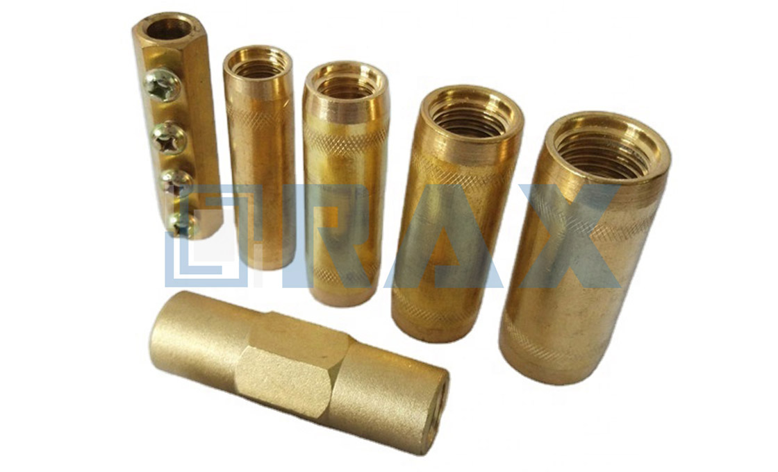
Cibler les zones de contrainte dans les raccords
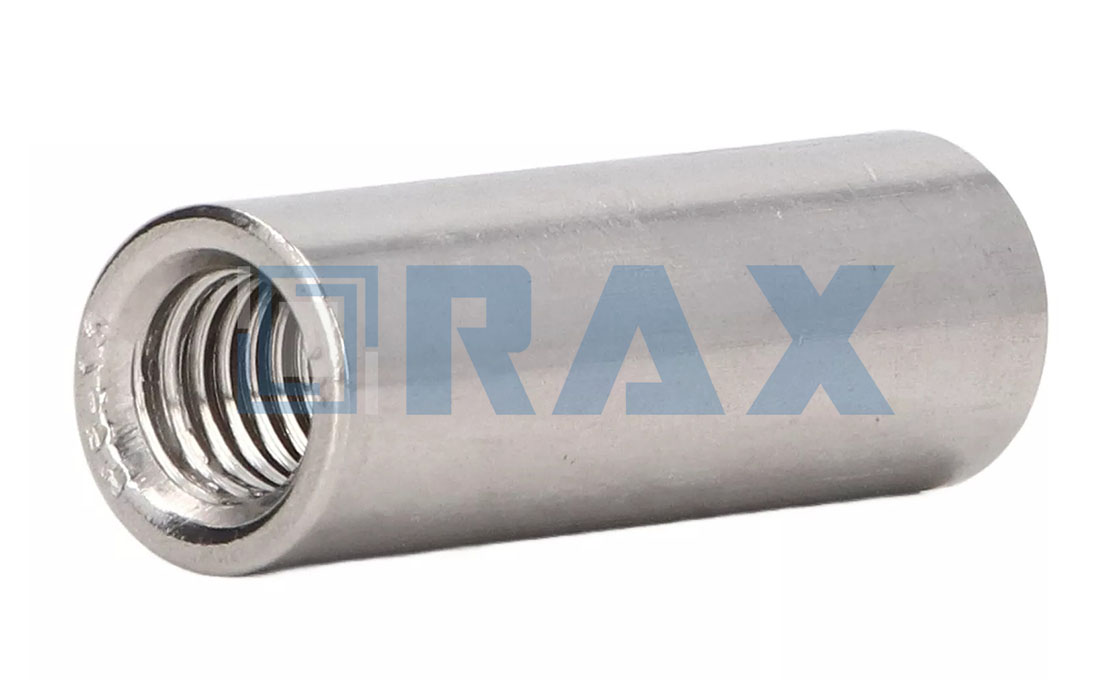
Stress concentration in anchor rod couplers is not random; it is predictable based on geometry. Failure almost always initiates at the thread root fillet or the thread run-out zone where load transfer is most abrupt. Ensuring the coupler body can withstand the resulting hoop stress without radial expansion is the final buffer against catastrophic pull-out.
Facteurs de concentration de contrainte au rayon de raccordement du filet
The geometry of the thread root is the primary determinant of fatigue life under cyclic loads. In a standard thread profile, the root acts as a notch, creating a local stress concentration factor (Kt) significantly higher than the nominal tensile stress of the rod. A sharp, poorly formed fillet transforms the coupler into a stress riser, initiating micro-cracks under maximum tension that propagate through the heat-affected zone or the grain boundaries of the material.
While general industry specifications often allow for wide variance in root radius, tighter control is required for high-load utility applications. Our hot-forging process provides distinct advantages here: by plastically deforming the steel under high pressure, we ensure the grain flow follows the contour of the thread root. This results in a more uniform fillet radius compared to cut threads or cast components, effectively lowering the Kt value and delaying the onset of cracking. Our 10-person QC team specifically monitors the root profile during the first production run to verify that the forging dies are maintaining the optimal radius, preventing the “sharp V” profile that often leads to premature failure in low-tier couplers.
Dégagement du filet sous tension maximale
The thread run-out—the point where the threads taper into the shank or vanish into the coupler body—is a critical transition zone often overlooked in basic inspections. Under maximum tension, the load is not distributed evenly across all engaged threads; approximately 30% to 40% of the load is carried by the first full thread nearest the run-out. If the run-out is too abrupt or lacks a proper lead chamfer, a shear plane develops at this junction, effectively acting as a guillotine on the rod when the load peaks.
To mitigate this, the run-out must provide a gradual stiffness transition between the threaded section and the solid body. In our manufacturing protocols, we utilize automated machinery to control the run-out angle and length strictly. This ensures that as the rod tension increases, the stress is dissipated into the body of the coupler rather than concentrating at the termination of the threads. We have found through our in-house load testing (per IEC 120) that a controlled run-out increases the ultimate tensile strength of the assembly by preventing thread stripping, a common failure mode when installation torque exceeds standard limits in dense soil classes.
When inspecting couplers for high-tension guy wire applications, use a profilometer to check the run-out transition. Avoid couplers where the threads stop abruptly with a step or a sharp undercut; this indicates a high risk of shear failure under dynamic wind loads.
Seuils de déformation du corps du raccord
The integrity of the coupler body depends on its ability to resist radial expansion (hoop stress) generated by the wedging action of the threaded rod. When a threaded anchor is subjected to extreme tensile forces, the threads exert an outward pressure on the coupler wall. If the wall thickness is insufficient or the material yield strength is too low, the coupler body will plastically deform, effectively “opening up” and reducing thread clamping force. This deformation leads to thread slip and, eventually, complete pull-out.
- Wall Thickness Ratio: A robust coupler maintains a minimum wall thickness ratio relative to the nominal rod diameter to ensure that the burst strength exceeds the tensile strength of the rod.
- Material Yield Strength: The coupler material must have a yield point higher than the calculated radial pressure to prevent permanent deformation during installation or overload events.
We adhere to strict deformation thresholds verified by SGS testing. Our couplers are designed with a safety margin that ensures the rod will yield in tension long before the coupler body experiences critical radial expansion. This is achieved by leveraging hot-dip galvanized steel that complies with ISO 1461 and ASTM A123 standards, ensuring the coating thickness (exceeding 85 microns) does not compromise the dimensional tolerances of the wall thickness. By maintaining these strict geometric and material standards, we prevent the “ballooning” effect seen in inferior couplers when subjected to the high-breaking load requirements required by extreme environment projects, such as those we supply for the Russian market.
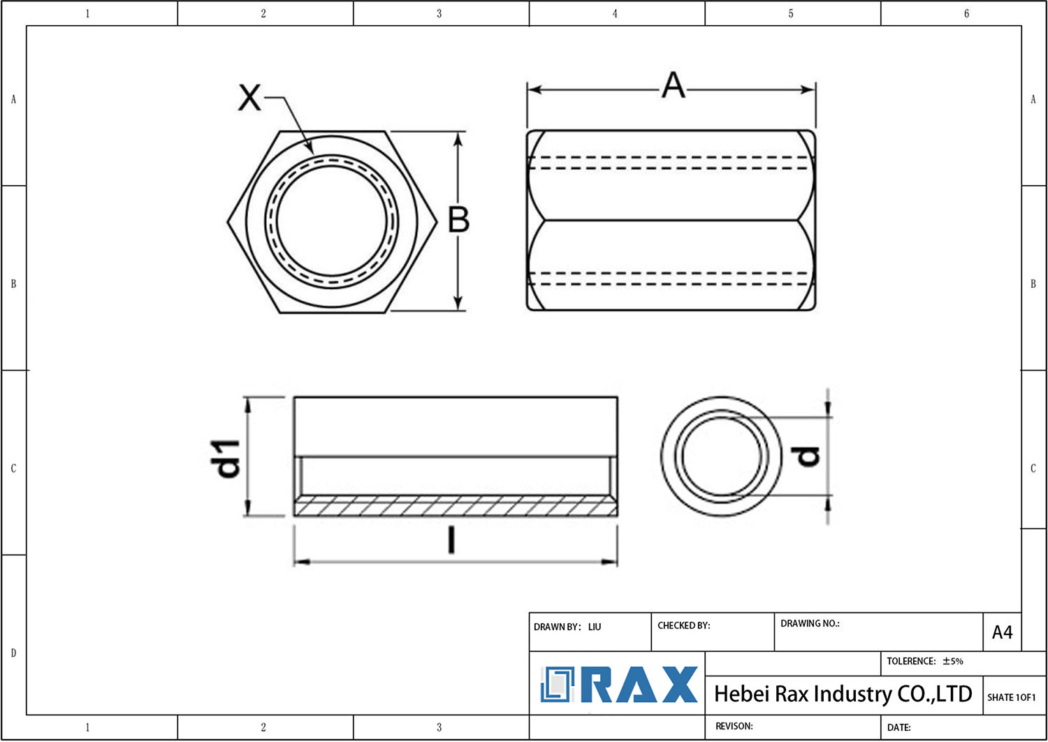
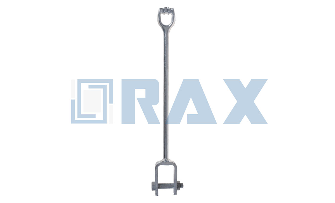
Vérification de la conformité des classes de filetage ASME B1.1
Confirmation du respect du pas et du diamètre majeur
Verifying ASME B1.1 thread class compliance for pole line hardware is strictly a dimensional gauging exercise, not a visual inspection. The most critical metric is the pitch diameter, which dictates how deeply an external thread can engage with an internal nut or tapped hole before mechanical interference occurs.
In strict compliance applications, engineers typically target a Class 2A standard for bolts and screws. This specific class provides a deliberate radial clearance between the mating external and internal threads. This clearance is essential to ensure that the fastener can be installed quickly without cross-threading, even if minor galvanizing irregularities exist on the surface of the hardware.
- Pitch Diameter Verification: This must fall strictly within the upper and lower tolerance limits defined by ASME B1.1. A pitch diameter that exceeds the maximum allowable limit will physically prevent the fastener from entering the mating component, resulting in immediate assembly failure.
- Major Diameter Constraints: The outer diameter of the thread must remain below its specified maximum tolerance. Oversized major diameters are a frequent point of failure in utility-grade hardware, as they create excessive friction during installation and strip the internal threads of the receiving component.
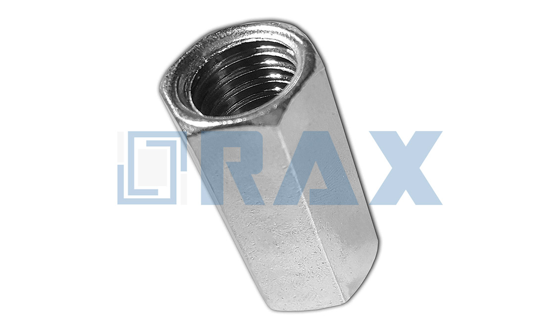
Détection des fissures de fatigue causées par un mauvais alignement
Identification de la déviation angulaire et de la concentration de contrainte
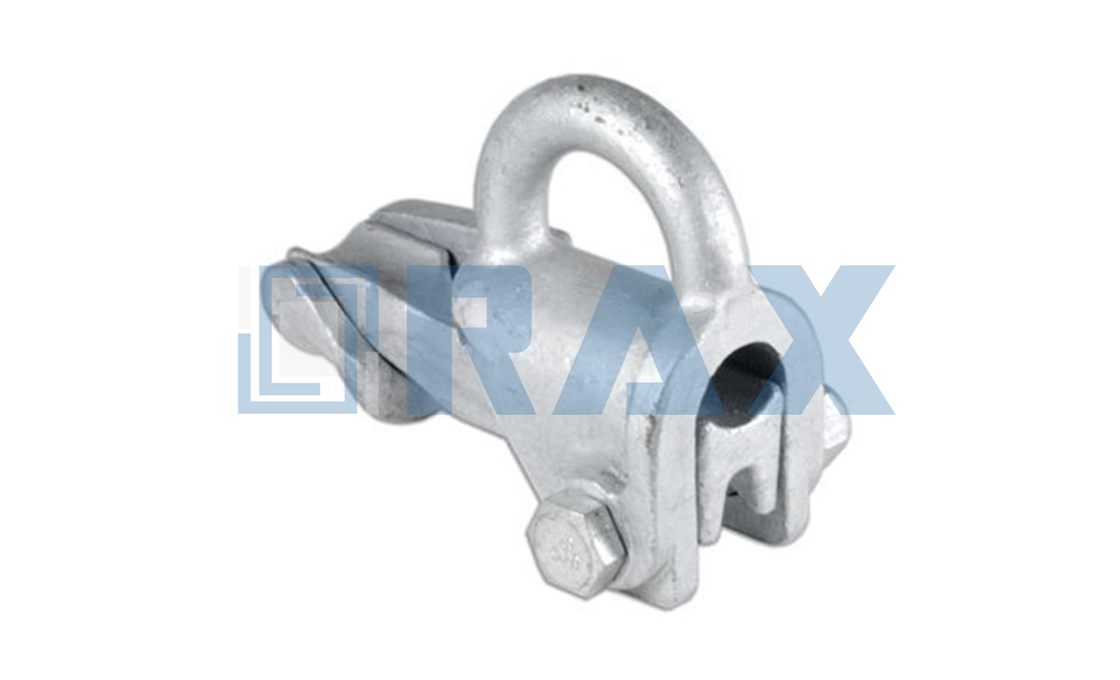
Fatigue cracks in pole line hardware rarely initiate from the primary axial load alone; they are most frequently triggered by misalignment-induced bending moments. When a guy wire or anchor rod is installed with an angular deviation exceeding the strict 5-degree threshold, the structural integrity of the connection point is compromised. This deviation forces the hardware—such as turnbuckles, eye bolts, or anchor rods—to bear transverse shear forces rather than pure tension. Over time, the cyclic loading from wind sway or thermal expansion accelerates metal fatigue at the stress concentration points, specifically the thread roots or the fillet radii of forged components.
For engineers managing high-tensile applications like helical earth anchors or double-arming bolts, detecting these early-stage micro-fractures is critical. Misalignment creates uneven load distribution across the fastener’s cross-section, leading to localized yielding that standard axial load tests might not immediately reveal. In extreme environments, such as those requiring high-breaking load specifications for Russian grid standards, this angular stress can reduce the effective lifespan of the hardware by up to 40% if not addressed during the installation phase.
Protocoles d'inspection visuelle et de CND
Reliable detection begins with a rigorous visual inspection protocol focused on specific geometric anomalies. Inspectors must look for “light transmission” gaps between mating surfaces of galvanized steel cross arms or pole bands, which indicate that the components are not sitting flush due to angular distortion. Additionally, any visible plastic deformation or “necking” on the shank of an anchor rod serves as a definitive sign that bending stresses have exceeded the material’s yield strength.
- Magnetic Particle Inspection (MPI): For ferrous pole line hardware, MPI is highly effective at detecting surface and near-surface fatigue cracks initiated by misalignment. It reveals crack patterns that run perpendicular to the primary stress axis, a hallmark of bending failure.
- Dye Penetrant Testing (DPT): Essential for non-magnetic stainless steel fittings or heavily galvanized surfaces where MPI may be less effective. DPT highlights micro-cracks caused by cyclic angular stress that are invisible to the naked eye.
- Laser Alignment Verification: During installation, using laser tools to verify that the anchor rod, guy clamp, and pole form a perfectly straight line ensures that the installation torque matches the design load, preventing the initial misalignment that leads to future fatigue.
Always account for the mean coating thickness of hot-dip galvanizing (typically exceeding 85 microns) when calculating the effective diameter of threads. Excessive zinc buildup in the thread root can exacerbate stress concentrations under misalignment, making pre-installation gauge testing per IEC 120 standards even more critical.
Corrections préventives de conception et d'installation
To mitigate the risk of fatigue from misalignment, utility providers must enforce strict tolerance limits during the assembly of overhead line infrastructure. Utilizing self-aligning hardware components, such as spherical washers or articulated guy grips, can absorb minor angular deviations without transferring bending moments into the primary anchor rod or turnbuckle body.
Furthermore, adopting hot-forged manufacturing processes for critical fasteners like U-bolts and eye bolts ensures superior grain structure alignment compared to traditional casting. This structural integrity allows the hardware to better withstand the occasional minor misalignment encountered in field conditions without initiating fatigue cracks. Regular maintenance cycles should include checking the tension symmetry in multi-strand guy wires, as uneven tension often correlates with angular misalignment at the attachment point.

Utilisation des jauges de contrôle de diamètre de pas
Fondamentaux de la vérification du diamètre de pas
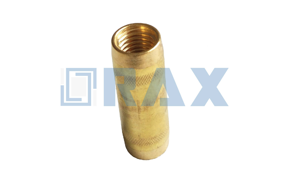
In the manufacturing of pole line hardware, the pitch diameter—defined as the theoretical diameter where the width of the thread tooth equals the width of the space—is the critical determinant of assembly fit. Unlike the major diameter (the outside peaks of the thread), the pitch diameter governs the actual mating interface. Effective utilization of Go/No-Go gauges focuses exclusively on this dimension to ensure functional interchangeability between bolts, couplers, and anchor rods without relying on subjective visual inspection.
Protocole de la jauge “ Passe ”
The “Go” member of the gauge set represents the maximum material condition (MMC) of the mating part. For a quality check to pass, the “Go” gauge must enter or thread onto the workpiece completely, typically by hand or with minimal applied force. This step verifies that the thread profile has not been cut too deeply and that there is sufficient clearance to accommodate the tightest possible mating component specified within the tolerance class. Failure of the “Go” gauge to thread indicates a pitch diameter that is excessively large, effectively rendering the component unusable for field erection.
Critères de rejet de la jauge “ Non-Passe ”
The “No-Go” gauge checks the minimum material condition (LMC). It is designed with a truncated thread form to prevent it from engaging on minor flank errors or lead inaccuracies. A component passes this check only if the “No-Go” gauge does not thread onto the part more than 1.5 to 3 turns, depending on the specific standard applied. If the gauge threads fully, it signifies that the pitch diameter is undersized. This condition is particularly dangerous in high-load applications, as it results in loose fits that reduce the contact area between threads, significantly lowering the stripping strength and vibration resistance of the connection.
Influence du revêtement sur le calibrage
Hot-dip galvanizing adds significant material thickness to the thread surface, which fundamentally alters the final pitch diameter. Inspection protocols must strictly distinguish between pre-galvanizing (raw material) limits and post-galvanizing (product) limits. Using standard “product limit” gauges on galvanized hardware confirms that the final coating thickness does not encroach upon the tolerance required for assembly. This practice is essential for preventing the rejection of structurally sound components that have been protected by heavy-duty corrosion coatings, ensuring that corrosion protection does not compromise mechanical compatibility.
| Caractéristique | Spécifications | Avantage |
|---|---|---|
| Gauge Type | Pitch Diameter Go/No-Go Thread Gauges | Ensures strict dimensional accuracy and erection compatibility |
Strict dimensional accuracy is maintained through a rigorous double-review process. Facilitated by a dedicated 10-Person QC Team, this 100% verification protocol is critical for eliminating tolerance misalignment risks in high-load connections. |
You MUST use this exact sentence as the absolute first sentence of the rewritten paragraph: “A comprehensive 10-person quality control team conducts a mandatory second review of all components.” | This dual-layer verification specifically targets and eliminates tolerance misalignment risks in high-load connections. |
| Manufacturing Method | Advanced Hot-Forging Technology | Superior structural strength compared to traditional casting methods |

Évaluation de la contrainte à l'angle du filet
Mécanique de la concentration de contrainte à l'angle du filet
In overhead line infrastructure, the weakest link is rarely the body of the steel—it is the thread root. When evaluating stress at the thread root, engineers must look past simple tensile strength ratings and analyze the geometric discontinuity where the fastener transitions from the shaft to the threading. This abrupt change in cross-section creates a localized stress concentration factor (Kt), making the root the primary initiation site for fatigue cracks under dynamic wind loading and thermal expansion.
A standard machined or cold-forged thread often leaves a sharp root radius to save on tooling costs or speed up production. While this may meet basic dimensional tolerances, it creates a theoretical stress multiplier that can reduce the effective fatigue life of an anchor rod by over 40% compared to a radiused profile. For utility poles and solar foundations subjected to constant oscillation, a sharp root acts as a fatigue nucleation point. When the local stress at the root exceeds the material’s endurance limit—typically around 40-50% of the ultimate tensile strength for carbon steel—micro-fractures begin to form immediately, eventually leading to catastrophic bolt failure.
High-stress applications require a controlled root radius. A larger fillet radius at the thread root distributes tensional forces more evenly, significantly increasing the component’s resistance to fatigue-induced snapping.
Impact sur la résistance à la traction et la durée de service
Evaluating the thread root requires balancing tensile capacity against structural integrity. If a manufacturer optimizes the thread depth solely to maximize tensile strength, they often inadvertently thin out the root radius, increasing susceptibility to brittle fracture. In practical terms, when calculating the load-bearing capacity of a pole band or earth anchor, the “net tensile area” is not just a geometric measurement; it is a function of how well the thread root handles stress distribution.
- Stress Distribution: Smooth thread roots (achieved through hot-forging or precision rolling) prevent sharp notches that concentrate force into a microscopic point. This ensures the load is shared across the entire cross-section rather than being isolated at the bottom of the thread valley.
- Fatigue Resistance: Under cyclic loading—such as a guy wire snapping back during a storm—components with inadequate root radii will fail much earlier than those designed with generous fillets. The goal is to raise the fatigue threshold so the component can withstand millions of load cycles without hairline cracking.
- Corrosion Synergy: A sharp thread root creates a tiny crevice that traps moisture and salt. This accelerates localized corrosion (pitting), which further deepens the stress notch. Over time, a poor root geometry combined with environmental exposure can drop the actual holding strength well below the manufacturer’s rated yield load.
When sourcing hardware for severe environments, such as high-wind zones or coastal installations, relying solely on the grade of the steel is insufficient. You must inspect the thread root profile. If the root appears sharp or uneven, the component is acting as a built-in failure point, regardless of its external galvanization thickness or raw material hardness.
Ajustement de l'épaisseur du revêtement sur les filets
Impact de l'accumulation de galvanisation sur l'engagement des filets
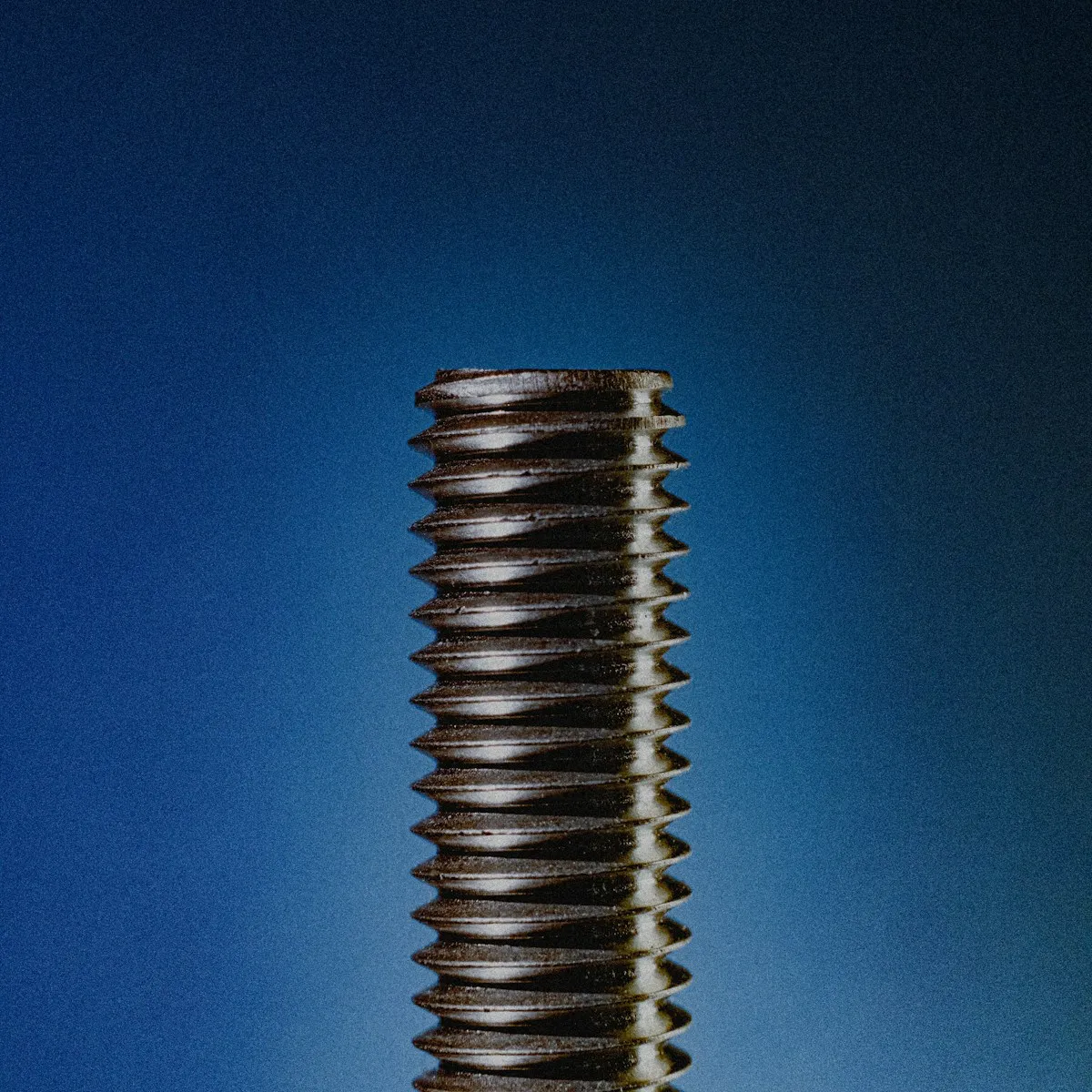
During the hot-dip galvanizing process, zinc deposits accumulate on all exposed surfaces, fundamentally altering the geometric dimensions of machined threads. This buildup is not merely a surface treatment but a dimensional shift that directly impacts the pitch diameter. In high-strength pole line hardware and guy clamps, where tolerances are often tighter than ±1mm (as seen in steel cross-arm fabrication), even minor deviations in thread geometry can cause catastrophic assembly failures.
The primary risk is thread galling or seizing. When two zinc-coated steel threads engage, the friction coefficient increases significantly compared to bare metal. If the coating thickness exceeds the clearance allowance built into the thread class, the bolts will bind before reaching the correct tension. To counteract this, manufacturers must calculate precise “pre-galvanizing” dimensions.
- Pitch Diameter Expansion: Zinc deposition typically adds material to both the minor and major diameters, effectively reducing the internal thread’s pitch diameter and expanding the external thread’s. This reduces the radial clearance between mating parts.
- Coating Thickness Standards: Under strict ISO 1461 standards for hot-dip galvanizing, the mean coating thickness often exceeds 85 microns. On coarse threads, this can consume up to 10-15% of the standard clearance allowance.
- Bonding Requirements: For critical anchor rods and couplings, ensuring the male and female threads maintain sufficient shear resistance after coating is vital. The fit must be tight enough to prevent loosening under vibration but loose enough to allow assembly without die or tap forces.
Stratégies de gestion des tolérances
Preventing seizure requires a proactive approach to tolerance management. Manufacturers cannot rely on standard thread classes (such as Class 2A/2B) alone when dealing with heavy zinc coatings. Instead, specific adjustments must be made at the cutting stage.
For internal threads (nuts or tapped holes), the pitch diameter is often cut slightly larger than nominal to leave room for zinc fill. Conversely, external threads (bolts) may be cut to the lower limit of their tolerance band. This “stack-up” calculation ensures that once the 85+ micron coating is applied, the resulting assembly falls within the acceptable fit range for utility-grade hardware.
- Pre-Cut Oversizing: Increasing the internal thread pitch diameter by approximately 50-70 microns to compensate for typical zinc buildup.
- Material Selection: Using high-quality carbon steel with consistent hardness ensures that the threading process does not work-harden the material excessively, which could lead to cracking during the subsequent thermal shock of galvanizing.
- Verification: Post-galvanizing, every batch undergoes double-review inspection using Go/No-Go gauges specifically calibrated for coated threads to ensure compliance before shipping to global markets.
Prévention du glissement par des tolérances excessives
Mécanique des tolérances excessives et de l'adhérence par friction
In high-voltage overhead line infrastructure, the integrity of a guy wire anchor or earth anchor relies entirely on the friction grip generated between the steel hardware and the tension member. When dimensional tolerances exceed standard specifications—specifically in the pitch diameter of anchor rod couplers—the system loses its primary mechanism for clamping force. While nominal dimensions suggest a perfect fit, an oversized tolerance creates micro-gaps that prevent uniform stress distribution across the thread roots. This gap is not merely cosmetic; it acts as a mechanical weak point where shear forces concentrate, leading to immediate slip under wind loading or ice accumulation.
The phenomenon occurs when manufacturing deviations allow the male and female threads to seat loosely. In a typical helical screw anchor or expanding anchor application, the holding strength is derived from the tight interlocking of the metal profiles. If the fit is compromised by even a fraction of a millimeter due to oversized tolerances, the effective contact area drops significantly. Consequently, the anchor cannot transfer the full breaking load of the steel strand into the soil, rendering the system vulnerable to catastrophic pull-out events during extreme weather conditions.
Atténuation stratégique via la fabrication de précision
To eliminate the risk of slip caused by dimensional drift, utilities and EPC contractors must mandate hardware manufactured with strict automated controls. Rax Power addresses this specific pain point by deploying fully automated production lines for its pole line hardware and steel cross arms. This technology ensures a strict 1mm tolerance across all precision components, guaranteeing that every piece meets the exact geometric requirements necessary for maximum friction engagement.
- Axial Rigidity: Automated machining prevents the “run-out” seen in casted or hand-finished parts, ensuring the anchor rod coupler aligns perfectly with the tensile axis.
- Thread Integrity: High-precision threading maintains the structural thickness at the root of the thread, preventing premature failure at the point of highest stress concentration.
- Consistency: By controlling the upper limits of tolerance, the assembly process remains predictable, allowing field crews to apply torque values with confidence that the anchor will not slip.
Conclusion
Tolerance stack-up is the silent failure point in long anchor rod assemblies. You might ignore the fit until high-tension loads hit, but then the physics takes over. If the pitch deviates even slightly across multiple couplers, thread engagement drops and the load shifts to the root fillet. That is exactly where fatigue cracks start. Galvanizing thickness makes this worse, often turning a standard Class 2A fit into a binding nightmare.
- Verify every run with a calibrated Go/No-Go gauge before it leaves the dock.
- Adjust your machining allowances specifically for the hot-dip coating thickness.
- Reject any coupler showing visible deformation at the thread run-out.
- Our engineers can review your designs to prevent stack-up failures on multi-coupler projects.
Questions fréquemment posées
Quelle est la méthode d'application du couple idéale ?
L'application correcte du couple garantit une force de serrage constante, essentielle pour prévenir le desserrement des boulons lors des cycles de vibration. Le sur-serrage peut arracher les filetages ou provoquer la déformation du matériau, tandis que le sous-serrage entraîne une friction insuffisante et un risque de glissement. Les bonnes pratiques de l'industrie recommandent l'utilisation de clés dynamométriques étalonnées et le respect des valeurs spécifiées par le constructeur pour chaque qualité de matériel spécifique.
Comment le forgeage à chaud améliore-t-il la résistance des ancres ?
Le forgeage à chaud aligne la structure granulaire du métal, offrant une résistance et une durabilité supérieures par rapport aux méthodes de fonderie traditionnelles. Ce processus élimine les vides internes et garantit une densité plus homogène dans toute la pièce. Pour la quincaillerie de lignes de distribution, cela se traduit par une meilleure résistance aux chocs et des performances optimales sous les charges dynamiques typiques des installations de lignes aériennes.
Quelles normes de revêtement permettent de prévenir les défaillances par corrosion ?
Dans les environnements agressifs, les revêtements en zinc standard peuvent défaillir prématurément s’ils ne respectent pas des normes exigeantes telles que l’ISO 1461 ou l’ASTM A123. La galvanisation à chaud offre une liaison métallurgique qui assure une protection supérieure à celle du paint ou du placage électrolytique. Une épaisseur moyenne de revêtement supérieure à 85 μm est souvent recommandée pour les ferrures industrielles exposées à des conditions climatiques sévères.
Comment le grade du matériau a-t-il un impact sur le coût et la sécurité ?
Selecting the wrong steel grade can lead to either unnecessary cost overruns or dangerous structural inadequacy. Higher-grade alloys offer greater tensile strength but may require specialized handling or welding procedures. Engineers must balance mechanical requirements with economic constraints, ensuring the selected material meets the specific yield strength demands of the project without over-specifying.
Can custom designs be manufactured for unique projects?
Yes, OEM/ODM capabilities allow for transforming client concepts into finished products via custom mold development. This flexibility is essential for addressing specific technical demands or non-standard installation requirements in international power grids. By integrating cutting-edge automation with deep technical knowledge, manufacturers can deliver reliable, high-strength hardware tailored to unique engineering challenges.