
An ADSS suspension clamp is the assembly that holds all-dielectric self-supporting fiber optic cable at intermediate poles, carrying vertical load while the cable hangs freely through the span. Get the wrong rod set, the wrong housing, or the wrong structure type, and the failure appears months later as jacket polish, micro-slippage, or crushed fibers. This guide covers what each component does, how sizing actually works, where the angle limits sit, and which field mistakes shorten service life. The sections below follow the order a line designer meets them.
RaxPower has manufactured pole line and overhead line hardware since 2003, and 170+ specialists now handle engineering, hot forging, and export supply for utility and telecom buyers. Production runs under an ISO 9001 quality system, and custom-engineered assemblies are available for non-standard spans or structures. No catalog tables appear here; the goal is a working understanding you can carry into a specification meeting.
What an ADSS Suspension Clamp Actually Is
An ADSS suspension clamp, often called a suspension set, is a preformed support assembly that carries the cable’s weight at an intermediate structure without gripping it like a termination. The cable is not squeezed hard between jaws. Instead, a cushioned nest of helical rods and elastomer holds the jacket the way you would carry a pipe in an open hand. The grip is firm enough to stop movement and soft enough to leave no marks.
All-dielectric self-supporting cable has no steel messenger wire to hang from. The jacket, the aramid strength yarns, and the cable’s own geometry carry every load: weight, ice, wind, and installer pull. That is why the suspension assembly is engineered around three ideas rather than around raw grip strength: spread the load, protect the jacket, and damp vibration. Among all ADSS cable fittings, the suspension clamp is installed most often, because every intermediate pole on a route needs one. For the wider family and how each part differs, see the main types of ADSS cable fittings.
Inside the Assembly: Rods, Housing and Inserts
A suspension set is built in layers, and each layer has one job. The inner rod set is the layer that touches the cable. Preformed from aluminum-clad steel or aluminum alloy wire, these helical rods wrap directly around the jacket, so pressure spreads along a long path instead of concentrating at points. A second, stiffer layer of outer rods lies over the first. Manufacturers such as PLP build this as a structural reinforcing rod set under an outer rod set, a double layer that cuts compression and bending stress under unbalanced lengthwise loads.
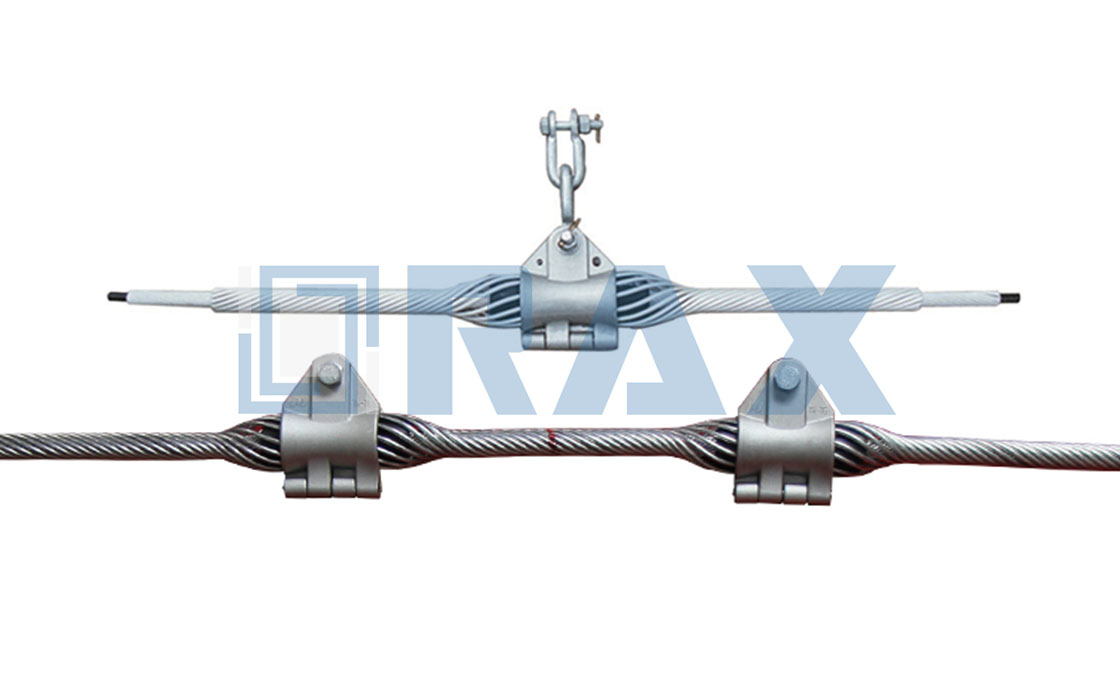
The housing is the visible part: an aluminum alloy shell, usually in two halves, that closes over the rod bundle and shapes the cable’s hanging curve. Resilient elastomer inserts line the housing. They cushion the rod set, absorb aeolian vibration before it reaches the glass fiber, and hold their flexibility through temperature swings, UV exposure, and years of compression. Galvanized steel bolts and lock washers pull the halves together. From the housing, a link fitting — a Y-clevis, ball hook, chain link, or anchor shackle — carries the vertical load down to the pole band or crossarm bracket.
How the Clamp Supports Cable at Tangent Structures
Tangent structures are the straight-line poles between dead-ends, and they define where suspension clamps belong. Picture the cable passing through the assembly in one continuous run. The rod nest grips the jacket radially while the housing takes the vertical load: dead weight, ice sleeves, and the downward pull of wind. The housing then hands that load to the structure. Nothing terminates, nothing reverses; the cable simply rests at a controlled height that preserves ground clearance and sag.
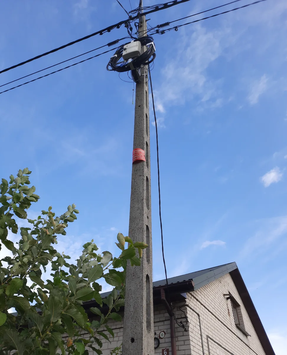
The elastomer makes this arrangement forgiving. ADSS cable moves constantly under temperature cycles and wind pressure, and a rigid grip would turn that movement into abrasion. The insert lets the cable creep a fraction under load while the rods follow, which is why the assembly behaves like a machine mount rather than a vice. Fiber attenuation stays stable because the housing’s designed curve respects the cable’s minimum bend radius. When the route changes direction, though, the load stops being purely vertical, and that is where angle ratings take over.
Sizing Variables: Cable OD, Span and Load Class
Three sizing inputs decide whether a suspension set survives its service life. The first is cable outside diameter, and the discipline here is simple: measure the actual drum with calipers instead of trusting the datasheet. Field failure analysis shows a clamp built for 12–14 mm cable cannot develop full contact on a 9.5 mm cable. Rods that bottom out before reaching full pressure, or that still turn by hand after installation, mark an undersized set.
The second input is span weight. Vertical load at the clamp is roughly cable weight per meter multiplied by the half-span on each side, then corrected for ice and wind cases in the line design. Long crossings therefore push the assembly toward longer rod sets and wider contact length, because a longer helix shares the load over more jacket. The third input is the structure itself: tangent pole, small angle, or dead-end. Each demands different hardware, and guessing wrong is the most expensive mistake on this list.
| Variable | What to confirm | Why it matters |
|---|---|---|
| القطر الخارجي للكابل | Caliper measurement on the drum, not the datasheet value | Rod inside diameter must match within about 1 mm for full contact |
| Span weight | Cable weight per meter over the span, plus ice and wind cases | Sets the vertical load the housing and insert must carry |
| Structure type | Tangent, angle, or dead-end classification for every pole | Chooses between single suspension, double suspension, and tension hardware |
| Environment | Coastal salt, industrial pollution, temperature range | Drives rod material and elastomer formulation choices |
Angle Limits and Double Suspension Assemblies
A suspension clamp is rated around a vertical load and a straight run, so every degree of line angle chips away at that assumption. As the route turns, the cable pulls sideways through the rod nest, and slip risk grows with the angle. Industry guidance from PLP puts a standard single suspension unit at line angles up to about 40 degrees. Between that ceiling and roughly 80 degrees, the standard answer is a double suspension: two assemblies, one on each side of the pole, sharing the load. Past 80 degrees, the structure should be treated as a dead-end and anchored with tension hardware instead.
The same logic explains why clamps fail when crews improvise. Until a clamp is matched to the true angle of the route, its rating is a guess. Installers who hang a standard set on a hard angle pole create a sideways component the insert was never shaped to resist. The cable creeps, the rods relax, and slippage follows within months. Checking route geometry before ordering hardware costs nothing and prevents the most common mis-application in the field.
Specifying ADSS Suspension Clamps for a Route?
Compare housing and rod combinations by cable diameter, span class, and angle rating on the product page, then match assemblies to your structure list.
Materials Behind Grip and Corrosion Resistance
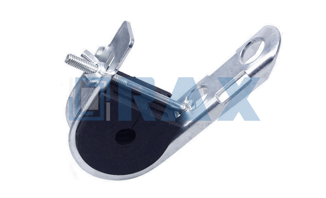
Material choices in a suspension set are about controlling three enemies: crushing, corrosion, and creep. Rods and housing are aluminum alloy or aluminum-clad steel. The clad construction puts steel strength inside an aluminum skin, so the wire bends easily around the jacket while resisting corrosion like bare aluminum. Housings stay aluminum as well, which keeps the assembly light enough to hang from a pole band without reinforcing the structure.
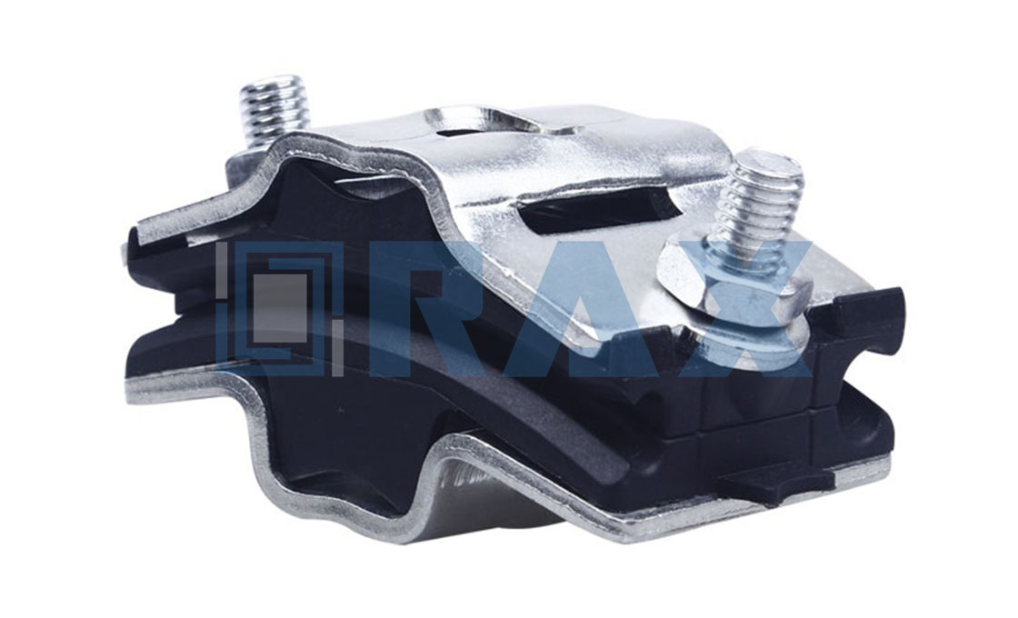
The elastomer insert carries its own specification. Formulations are chosen for UV resistance, weathering, and low compression set, because an insert that takes a permanent dent stops spreading pressure and starts shielding small bands of jacket. Steel hardware — bolts, lock washers, clevises, and shackles — is hot-dip galvanized to survive rain, coastal salt, and decades of contact with the aluminum body. Hard metallic jaws never touch an ADSS jacket anywhere in a correctly specified assembly; every interface is either aluminum, elastomer, or galvanized steel acting on another metal part.
Pairing the Clamp with Armor Rods
Armor rods and suspension clamps answer the same question — how to keep a moving, tensioned cable from wearing at one point — at different scales. A preformed suspension set already contains its own protection layer: the inner rod wrap spreads load over 600–1200 mm of jacket, against the 20–30 mm a bare jaw would press. That spread is why the same field analysis warns never to clamp an ADSS jacket directly; a bare interface concentrates stress so sharply that slippage can begin within weeks. For the wider protection logic around ADSS lines, the guide to ADSS hardware safety features covers the topic from the cable’s point of view.
Rod condition decides whether that protection keeps working. Corrosion, pitting, or fatigue fractures in the rod set lower the assembly’s effective grip. The cited analysis recommends replacing any set with more than roughly a tenth of its rods corroded. Spiral direction matters too: a rod wound in the wrong hand loosens under tension instead of tightening. In our experience, sourcing suspension hardware and rod accessories as one matched system removes most of these mismatch risks before the crate is even opened.
Failure Modes from Mis-Application in the Field
Most suspension clamp failures trace back to selection or installation, not to the hardware itself. ZTO Cable’s failure analysis attributes roughly 80% of ADSS clamping failures to installation practice, citing a tension-clamp case. The recurring failure patterns are consistent enough to list:
- Diameter mismatch — rods sized from a datasheet instead of a measured jacket never reach full contact pressure.
- Angle mis-application — a tangent-rated set hung on a hard angle creeps sideways and polishes the jacket.
- Over-torqued housing bolts — grip comes from the rod helix, and crushing the insert creates a permanent low spot.
- Thermal cycling — aluminum and steel expand at different rates, so unchecked bolts relax through repeated 60 °C swings.
- Damaged rod sets — corroded or wrongly handed rods give up grip long before the housing shows anything.
Diagnosis is mostly visual. A shiny, polished band of 5–15 mm just outside the rod ends is the classic signature of micro-slippage, because a polished jacket holds less friction and slips faster. The full root-cause breakdown of clamping failures is worth reading before any crew reuses hardware from an old job.
A Field Checklist for Clamp Selection
Run every route through the same five checks before hardware is specified:
- Measure cable OD on the drum with calipers, and match the rod set range within about 1 mm.
- Calculate vertical load from span weight, ice, and wind cases, then compare it with the assembly’s rating class.
- Classify every structure: tangent, angle up to about 40 degrees, double suspension to about 80 degrees, dead-end beyond.
- Choose rod material for the environment, from aluminum alloy wire to aluminum-clad steel for heavier spans.
- Confirm link hardware — Y-clevis, ball hook, or chain link — against the pole band or bracket actually fitted.
Once the five checks are done, confirm housing and rod combinations against the ADSS suspension clamp product page and request dimensional drawings before committing a route-wide order. Keeping rods, inserts, and housings within one tested system matters more than any single number on a datasheet.
The Takeaway for Line Designers
A suspension clamp looks like the simplest fitting on the route, and that impression is exactly what makes it dangerous to specify casually. The assembly works only when rod set, insert, housing, and structure type all agree with the cable and the geometry above it. Measure the jacket, respect the angle ceiling, keep rod sets healthy, and the same clamp will hold fiber safely for decades.
Key engineering facts about the ADSS suspension clamp:
- A standard single suspension unit covers line angles up to about 40 degrees; a double suspension extends coverage to about 80 degrees.
- Preformed rods spread clamping load over roughly 600–1200 mm of jacket, compared with 20–30 mm for a bare clamp interface.
- Match the rod set to the measured cable OD within about 1 mm; a set sized for 12–14 mm cable cannot fully grip a 9.5 mm cable.
- A polished band of 5–15 mm just outside the rod ends is the visual signature of micro-slippage.
- Typical assemblies combine an aluminum alloy housing, UV-stable elastomer inserts, aluminum-clad steel or aluminum alloy rods, and hot-dip galvanized link hardware.
- ZTO Cable’s analysis attributes roughly 80% of ADSS clamping failures to installation practice rather than product defects.
RaxPower manufactures ADSS suspension and anchoring hardware within a pole line range exported since 2003, produced under an ISO 9001 quality system and available as custom-engineered assemblies for unusual spans. Treat the clamp as a system component rather than an accessory, and it will outlast every other fitting on the pole.
عازل مثبت على العمود يمسك بالمواسير الرأسية على مسافة ثابتة من سطح العمود، مما يحمي الكابلات ويحافظ على الفصل عن الموصلات والمعدات الأخرى.
هل يمكن استخدام مشبك التعليق على عمود زاوية؟
فقط ضمن نطاق زاويته المصنّف. تغطي وحدة التعليق المفردة ما يقارب 40 درجة من زاوية الخط، وتمتد وحدة التعليق المزدوجة هذا المدى إلى نحو 80 درجة. تحتاج الزوايا الأعلى إلى عتاد شدّ، لأن مجموعة التماس لا تستطيع مقاومة السحب الجانبي بأمان.
كيف أعرف حجم قضيب الربط المناسب لكابل ADSS الخاص بي؟
قس القطر الخارجي الفعلي للكابل بالكالبر على البكرة، ثم طابق قطر مجموعة القضبان ضمن حوالي ملليمتر واحد. إذا أمكن تدوير القضبان باليد بعد التركيب، فهذا يدل على أن المجموعة أصغر من المقاس المطلوب.
هل تحتاج مثبتات تعليق ADSS إلى قضبان درعية؟
مجموعات التعليق المسبقة التشكيل تغلف الغلاف بالفعل بقضبان وقائية، لذا لا حاجة عادةً إلى قضبان درع منفصلة. الأهم هو حالة القضبان: فالقضبان المتآكلة أو المنقطة بالتآكل أو خاطئة الاتجاه تقل من قوة الإمساك ويجب استبدالها كمجموعة كاملة.
What is the difference between a suspension clamp and a tension clamp?
A suspension clamp carries vertical load at intermediate poles while the cable passes through continuously. A tension clamp anchors the full span tension at dead-ends, angles, and terminations. They are sized and installed differently and are not interchangeable.
Why does the cable polish or slip inside the clamp?
Polishing signals micro-slippage, usually from diameter mismatch, angle overload, or relaxed hardware. Once the jacket surface burnishes smooth, friction drops and slipping accelerates, so a polished band outside the rod ends calls for immediate inspection.