
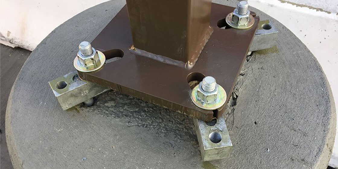
La integridad estructural en el hardware de servicios públicos depende de la capacidad del acoplador para mantener la cohesión de la junta bajo tensión extrema. Un acoplador de perno de anclaje une dos varillas roscadas para transferir cargas de tracción al suelo. El acoplador que mantiene unida la junta no tiene segunda oportunidad; cuando la junta falla, toda la estructura falla.
Forjado en caliente elimina la zona afectada por el calor presente en los diseños soldados. Un flujo de granos continuo. Cero puntos débiles donde se inician las grietas. Esta única elección de fabricación duplica la vida útil en condiciones corrosivas del suelo.
Los acopladores de alta resistencia previenen la extracción catastrófica mediante rigurosas pruebas de carga, protocolos de resistencia a la fatiga y análisis detallado de modos de fallo. Este desglose técnico capacita a los directores de adquisiciones para especificar hardware confiable que cumpla con estrictos estándares de cumplimiento utilitario.
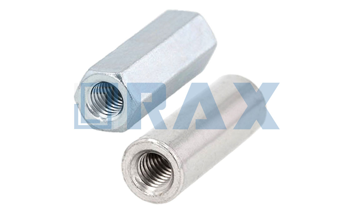
Implicaciones del grado del material en el rendimiento
Seleccionar la aleación correcta dicta si un acoplador cede prematuramente o falla catastróficamente por corte. Entender las distinciones de ASTM es no negociable para la confiabilidad a escala de servicios públicos.
La selección del grado del material define la integridad estructural de los acopladores de varilla de anclaje, con ASTM A108 y ASTM A563 que cumplen roles mecánicos distintos. Elegir el grado incorrecto introduce riesgos severos, que van desde el desgaste de roscas hasta la fractura súbita y frágil bajo cargas extremas de la red.
ASTM A108 vs A563: Distinciones críticas para hardware de servicios públicos
ASTM A108 especifica barras de acero al carbono de alta calidad destinadas al mecanizado y torneado. En el contexto del hardware de líneas de postes, A108 proporciona un punto de partida metalúrgico impecable y libre de defectos. Garantiza tolerancias ajustadas en redondez y rectitud, lo cual es esencial al perforar roscas internas de precisión para acopladores de varilla. Sin embargo, A108 es estrictamente una especificación de materia prima; no exige la dureza mecánica final requerida para aplicaciones de sujetadores de alta tensión a menos que se someta posteriormente a tratamiento térmico.
En contraste, ASTM A563 define las propiedades mecánicas de tuercas y componentes roscados de acero al carbono y aleado. Cuando especificamos grado A o grado DH (Endurecido Directo) de A563 para nuestros cuerpos de acoplador, garantizamos una resistencia a la tracción específica y capacidad de carga de prueba. A563 asegura que el hardware terminado pueda soportar las fuerzas axiales masivas ejercidas por los cables de amarre durante eventos de tormenta sin sufrir roscado cruzado o agarrotamiento. El uso de componentes de grado A563 aborda directamente la necesidad del servicio público de capacidades de carga estandarizadas y predecibles.
- ASTM A108: Se enfoca en la calidad de la barra de acero sin procesar (bajas impurezas, tolerancias ajustadas) antes del mecanizado.
- ASTM A563: Dictates the final mechanical performance (tensile strength, hardness) of the manufactured nut or coupler body.
- The Synergy: High-end couplers utilize A108 bars machined to meet or exceed A563 mechanical grades, ensuring both geometric precision and raw strength.
Efectos del tratamiento térmico en la ductilidad y resistencia a la fractura
The transition from raw steel to functional hardware relies heavily on heat treatment. Improper thermal processing is the most common cause of catastrophic hardware failure in overhead line installations. While increasing hardness improves tensile strength, it often simultaneously reduces ductility, pushing the material toward brittle fracture.
Through our rigorous hot-forging process, we manipulate the grain structure of the steel to align with the component’s shape. This is immediately followed by controlled quenching and tempering. Quenching rapidly cools the steel to achieve extreme hardness, but this renders the component dangerously brittle. Tempering then reheats the steel to a lower temperature to relieve internal stresses, thereby restoring ductility.
In our laboratory, we strictly monitor the balance between yield strength and elongation. Our dual-review inspection protocol ensures that every batch of couplers maintains a ductile microstructure capable of absorbing kinetic energy. This balance is what allows our hot-forged, A563-compliant components to survive the extreme environmental cycles faced by power grids in regions like Northern Europe and North America.
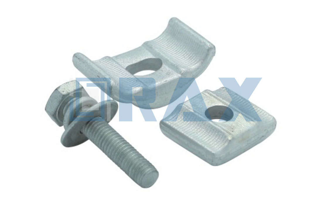
Requisitos de resistencia a la tracción según normas
For heavy-duty pole line hardware, especially when transitioning between structural steel components and deep-earth groundings, verifying tensile capacity and material integrity is non-negotiable. While building codes like ACI 318 govern concrete interactions, they do not dictate the metallurgical standards for the forged steel hardware used in our overhead line infrastructure. Therefore, our engineering approach relies on specialized power transmission standards—specifically looking at how ASTM F1554 dictates bolted assembly compatibility—to ensure the final assembly does not fail under extreme wind loading or heavy ice accumulation.
ASTM F1554 y compatibilidad de alta resistencia
When designing complex guyed pole structures, engineers often look to ASTM F1554 as a baseline for understanding material limits. This standard specifically categorizes anchor bolts into three grades based on yield strengths—Grade 36, 55, and 105. While our products operate outside the strict definition of building foundation bolts, applying the Grade 105 tensile framework allows us to validate the performance of our high-breaking-load helical anchors and forged couplers in severe climates, such as those seen in Russian utility tenders or South American mega-projects.
- Yield Strength Matching: The hardware must not be the weak link in the chain. Using our hot-forging process, we ensure the tensile strength of our couplers and clamps meets or exceeds the rated capacity of the rods they connect, preventing shear failures.
- Thread Engagement Standards: Proper compatibility requires precise thread profiling. Our automated machining guarantees that the pitch and depth align perfectly with standard threaded rods, eliminating the risk of stripped threads during high-torque installation.
Abordando la interfaz estructural-suelo
A common pitfall in utility procurement is mixing commercial fastener standards with structural requirements. If a project specifies building-grade materials for a power pole anchor, the result is often premature corrosion or inadequate ductility. We avoid this ambiguity by strictly adhering to our internal QC protocols, ensuring that every component—from the guy clamp to the helix—is engineered for power grid applications rather than static civil construction.
Verifying material grade through 100% double-review inspections ensures carbon steel batches meet yield targets before leaving the facility. This rigorous internal QC protocol eliminates ambiguity, guaranteeing that every component possesses the necessary ductility and strength for power grid applications rather than static civil construction.
Por qué nuestra ventaja manufacturera es importante aquí
At Rax Power, we integrate these rigorous standards directly into our production flow. Unlike suppliers who might cast cheaper parts that lack ductility, our exclusive use of hot-forging creates a continuous grain structure. This is crucial for meeting high-tensile compatibility checks, as it prevents micro-fractures that could occur if the hardware were forced to handle loads beyond its certified breaking point. We don’t just manufacture parts; we engineer the safety margins that keep utility grids operational during extreme weather events.
| Standard / Test Method | Parámetro | Requirement | Benefit |
|---|---|---|---|
| IEC 120 | Load Testing | In-house rigorous load testing for all anchor rods and couplers | Ensures full load capacity development and safe working loads up to 38,000 lbs |
| ASTM A153 | Coating Thickness | Mean coating >85 microns (Hot-Dip Galvanizing) | Surpasses minimums for extended lifespan (10-15 years) in aggressive environments |
| ASTM A563 | Material y construcción | High-strength carbon steel with hot-forged single-piece construction | Eliminates heat-affected zones and provides superior strength compared to casting |
| Internal QC Protocol | Quality & Safety | 2:1 Safety Factor with Double-Review Inspection Protocol | Guarantees dimensional accuracy and reliability for global utility markets |
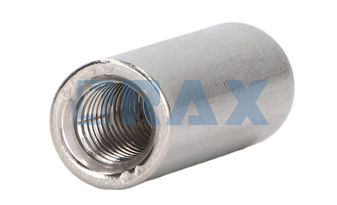
Metodologías de pruebas de carga
Pruebas de carga: el estándar no negociable para la confiabilidad de la red
Proof load testing serves as the mandatory stress simulation verifying that pole line hardware withstands maximum working loads without permanent deformation. Acting as the final gatekeeper for structural integrity, this step is more than a quality check; it is the critical mechanism for validating IEC 120 compliance.
In the utility sector, the gap between a certified product and a field-ready component often lies in the rigor of load testing. Many manufacturers rely on theoretical calculations or batch sampling that leaves significant risk exposure. We strictly adhere to IEC 120 standards for our testing protocols. This standard defines the specific gauge and load testing requirements that ensure dimensional accuracy and structural integrity under tension. Our facility conducts these rigorous load tests in-house, meaning we control the data from the machine to the report, eliminating the common industry practice of outsourcing verification to third-party labs that may not understand the specific loading conditions of overhead lines.
The methodology involves applying a specific tensile load—typically higher than the rated working load—to the hardware for a set duration. The pass criteria are strict: zero permanent set and no functional deformation. We utilize a dedicated 10-person QC team to oversee this process. Unlike standard factory setups where inspection is an afterthought, our team monitors every production stage. Every unit undergoes a double-review process before packaging, ensuring that the proof load data matches the physical output 100% of the time.
Impacto de los métodos de fabricación en los resultados de las pruebas
The validity of a proof load test is inextricably linked to how the hardware is manufactured. A proof load test will ruthlessly expose the weaknesses of sub-par construction methods, particularly in anchoring solutions. We utilize forjado en caliente technology to produce our single-piece anchor rods and helixes. This process refines the grain structure of the steel, creating a component with superior tensile strength and uniformity.
Conversely, competitors relying on welded designs often face failure points during proof load testing. The heat-affected zones (HAZ) created by welding alter the metallurgical properties of the steel, creating weak spots where the material can become brittle. Under the high stress of a proof load test, welded helixes are prone to shearing off—a failure mode that is virtually eliminated with our hot-forged single-piece construction. By removing the weld from the equation, our test results consistently show performance stability that welded assemblies simply cannot match, particularly in extreme environments requiring high-breaking loads.
Verificación de la integridad de la protección contra la corrosión
Proof load testing also serves as a proxy for the quality of the protective coating. If the galvanizing process is flawed, the mechanical stress of the test can cause flaking or cracking, exposing the underlying steel to corrosion. We apply leading hot-dip galvanizing technology compliant with ISO 1461, ensuring a mean coating thickness that exceeds 85 microns.
This thickness surpasses the minimum requirements of standards like ASTM A153. During our internal testing, we verify that this heavy coating adheres firmly even under load, ensuring the long-term lifespan of the hardware. Furthermore, all our processes and final products are subject to SGS verification. This independent auditing confirms that our proof load methodologies and our galvanizing quality meet global benchmarks, providing wholesalers and utility project managers with the assurance that the hardware delivered to the job site is exactly what was specified in the tender.
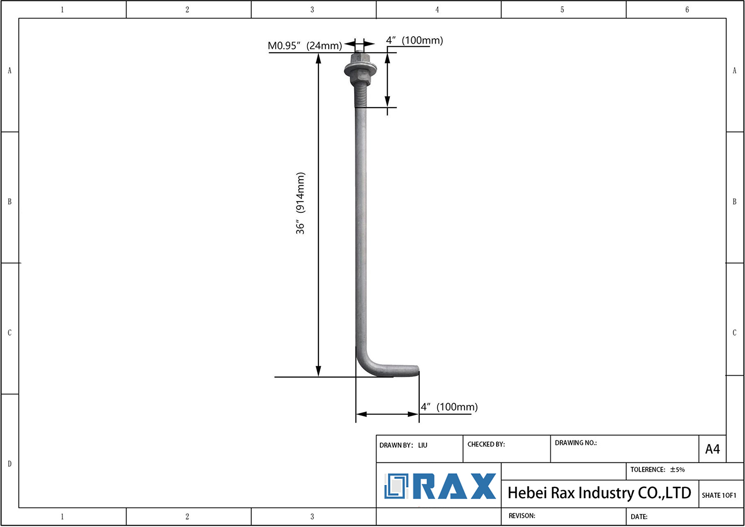
Protocolos de validación de resistencia a la fatiga
Monolithic hot-forging bypasses the structural weak links inherent in welded assemblies, effectively eliminating cyclic fatigue failure points.
In the overhead power transmission sector, fatigue failure is rarely a result of sudden overload; it is the slow, insidious result of cyclic stress acting upon structural discontinuities. For heavy-duty helical and no-wrench screw anchors, the most vulnerable point in a competitor’s assembly is typically the weld seam connecting the helix blade to the central shaft. Under constant wind-induced conductor oscillation or seismic micro-movements, these welded zones suffer from thermal degradation and stress concentration, eventually leading to brittle shearing.
To validate fatigue resistance and ensure absolute structural continuity, Rax Power rejects conventional welding entirely in favor of industrial hot-forging. Our validation protocol focuses on the elimination of the Heat-Affected Zone (HAZ), which is the primary catalyst for metallographic weakening in welded anchors. By utilizing a single-piece hot-forged construction, the metallurgical grain structure flows continuously along the contours of the anchor, maintaining uniform tensile strength across the entire component.
La debilidad estructural de las hélices soldadas
Most mass-produced helical anchors rely on robotic or manual welding to attach the helix plates to the shaft. While faster to produce, this introduces two fatal flaws regarding long-term fatigue resistance:
- Thermal Degradation: The intense heat required to weld the helix alters the crystal lattice of the base metal at the joint, creating a localized area of brittleness.
- Geometric Stress Risers: Weld beads create microscopic unevenness on the shaft. Under cyclic loading, these imperfections act as starting points for crack propagation, drastically shortening the operational lifespan of the anchor.
El estándar de validación de forjado en caliente de Rax Power
Our engineering team validates fatigue resistance through a combination of metallurgical continuity and rigorous in-house gauge testing. Because we forge the anchor as a single piece of carbon steel, there is zero risk of the helix shearing off the shaft due to weld failure, even under extreme torque loads during installation or severe lateral forces post-installation.
The durability of this forged bond is further protected by our adherence to ISO 1461 standards for hot-dip galvanizing. While standard galvanized coatings often sit at the bare minimum of 50 microns, our automated galvanizing process consistently achieves a mean coating thickness exceeding 85 microns. This dense metallurgical bond prevents corrosive pitting—a major accelerant of fatigue cracks—from compromising the structural integrity of the forged steel over the asset’s lifespan.
Métricas de pruebas cuantificables y de cumplimiento
Every batch of forged anchors undergoes rigorous load testing compliant with IEC 120 standards, enforced by a dedicated 10-person QC team. This team mandates a double-review inspection protocol, ensuring that 100% of the products receive a second independent inspection prior to packaging to eliminate any dimensional deviations that could compromise stress distribution.
Furthermore, all forging processes and material grades are SGS tested and verified. This allows utility operators and EPC contractors to confidently match our forged anchors to high-breaking load requirements for extreme environments—such as those frequently encountered in Russian or South American utility grids—without fearing catastrophic cyclic failure.
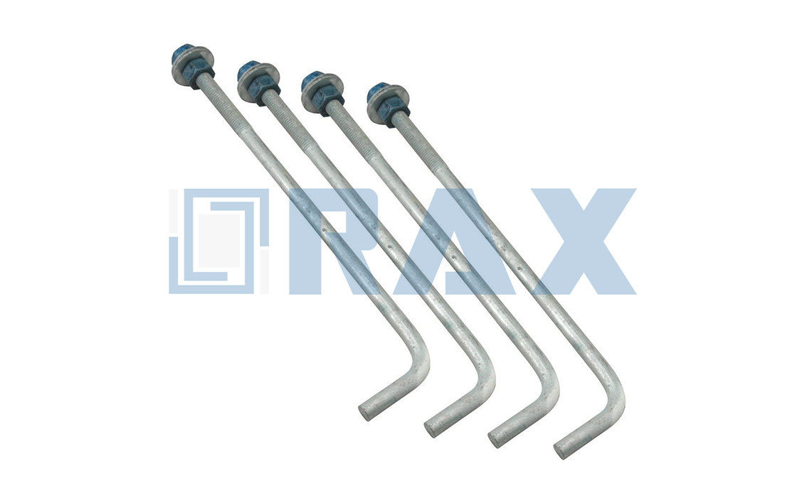
Interpretación de la prueba de extracción
Accurate pull-out test interpretation requires analyzing the load-displacement curve rather than focusing solely on the ultimate failure load. The critical distinction lies in identifying the transition from elastic deformation to plastic deformation; an anchor exhibiting significant permanent elongation below the working load limit is considered a failure, regardless of its peak tonnage.
Descifrando la curva carga-desplazamiento
A common mistake in the industry is fixating solely on the “Ultimate Breaking Load.” While this number looks impressive on a spec sheet, it tells you nothing about the anchor’s performance under standard operating conditions. Effective interpretation demands analyzing the relationship between applied load and anchor displacement. You must identify the exact point where the anchor shifts from elastic deformation (temporary stretching) to plastic deformation (permanent elongation).
If the test report shows the anchor stretching significantly before reaching its rated working load, you are looking at a defective unit or substandard material. In our experience with high-tension utility projects, any anchor that fails to return to its original length after a load test is a liability waiting to happen. This is why we strictly adhere to IEC 120 gauge testing protocols in our facility, ensuring that dimensional integrity is maintained under stress.
Diferenciando el fallo del ancla del fallo del suelo
Determining whether the steel component or the surrounding soil failed is the critical insight separating quality control issues from site engineering problems.
- Soil Failure (Pull-out): The anchor eye or rod remains straight, but the entire assembly pulls out of the ground. This indicates the soil shear strength was exceeded, not the anchor’s structural limit. The anchor “passed”; the site survey “failed.”
- Anchor Failure (Structural): The rod bends, the eye elongates, or the helix shears off. This is a manufacturing defect.
We frequently see competitors’ welded anchors suffer from helix shearing during high-torque installation or loading tests because the weld creates a heat-affected zone. By utilizing a hot-forged single-piece construction, we eliminate this weak point. Our testing confirms that the forged helix integrates seamlessly with the rod, ensuring that if a failure occurs, it is almost always due to soil mechanics rather than a metallurgical defect in the hardware.
Autenticación de datos de prueba: el protocolo “Detector de BS”
When evaluating suppliers, treat generic test reports with skepticism. A single page with a high “kN” rating and no context is useless. You need to see the raw data trail. We mandate that our 10-person QC team logs every incremental load step, recording the exact displacement at each stage. This data is archived and subjected to our double-review process, where 100% of products are inspected twice against these test baselines before packaging.

Análisis de modos de fallo
Weld-zone fatigue in earth anchors and inadequate galvanizing leading to premature corrosion are the primary vectors for field failures in pole line hardware.
Corte inducido por soldadura y desprendimiento de hélice
A critical, yet often overlooked, failure mode in earth anchors is the shearing of the helix during high-torque installation. When manufacturers utilize traditional welding methods to attach the helix to the rod, they inevitably create a “heat-affected zone” (HAZ). This area structurally compromises the steel, making it brittle and highly susceptible to cracking under the torsional stress required to penetrate dense or rocky soil. If the weld integrity fails, the anchor loses holding capacity immediately, resulting in costly re-drilling and project delays.
We have engineered a solution to bypass this risk entirely. By utilizing hot-forged, single-piece construction for our No-Wrench Screw Anchors, we eliminate the weld joint completely. This process ensures the grain flow of the steel remains continuous and unbroken by thermal stress. In our experience, this superior structural integrity significantly reduces the risk of helix shearing, even in extreme environments where high-breaking load requirements are non-negotiable.
Deslaminación del recubrimiento y corrosión del sustrato
Surface corrosion is the most persistent threat to the longevity of pole line hardware. Failure in this mode often begins with microscopic porosity in the galvanizing layer. If the coating thickness is inconsistent or below the mean standard, moisture ingress creates micro-pits of red rust on the substrate. This “rust jacking” eventually leads to section loss, reducing the cross-sectional area of the hardware and causing sudden fracture under load—often years before the projected service life ends.
To neutralize this failure vector, we strictly adhere to ISO 1461 hot-dip galvanizing standards. Our process achieves a mean coating thickness exceeding 85 microns, surpassing the minimums often found in standard ASTM A153 compliant products. This dense, smooth finish acts as a strong barrier against aggressive soil and atmospheric conditions. We have verified through internal testing that this specification typically extends asset lifespan by 10–15 years compared to lower-cost alternatives with thinner coatings.
Inestabilidad dimensional y concentración de tensiones
In the context of overhead line infrastructure, dimensional variance is not just a nuisance; it is a structural hazard. Components like steel cross arms and pole bands with loose tolerances create uneven load distribution across the pole structure. These “stress concentration points” become initiation sites for fatigue cracks, which propagate rapidly under wind load and vibration. For utility projects requiring high precision, relying on manual fabrication introduces a high probability of geometric mismatch and eventual mechanical failure.
We mitigate this through high-precision automated production. For our steel cross arms, we enforce a strict 1mm tolerance that manual shops simply cannot match at volume. additionally, our 10-person QC team implements a double-review protocol: 100% of products are inspected twice before packaging. This rigorous filter ensures that dimensional deviations never leave the factory floor, protecting your supply chain from the hidden costs of non-conforming hardware.
- Heat-Affected Zone (HAZ): The primary point of failure in welded anchors; eliminated via our single-piece hot-forging process.
- Coating Thickness: We guarantee a mean galvanizing thickness of >85 microns (ISO 1461) to prevent rust jacking.
- Tolerance Control: Automated machinery ensures a 1mm tolerance on cross arms to prevent uneven load distribution.
- QC Protocol: Double-review inspection on 100% of units to catch stress concentration defects before shipment.
Criterios de selección basados en la carga
Correspondencia entre la capacidad del acoplador y la resistencia de la varilla
When designing an anchor rod system, simply bolting two pieces of steel together does not guarantee structural continuity. The mechanical coupling must match the load-bearing capacity of the parent rod to prevent the weakest link from becoming the failure point of the entire foundation. For critical overhead line infrastructure, the coupler’s Safe Working Load (SWL) dictates the maximum operational stress the system can endure.
A common pitfall in procurement is selecting a standard commercial coupler that falls short of the rod’s proof load. While some generic couplers on the market may limit the system’s potential, we design our couplers to safely handle loads up to 38,000 lbs. This capacity ensures that even in deep installations where multiple rod extensions are required, the connection point does not become a bottleneck for load transfer. We achieve this by utilizing high-strength alloy seamless tubing rather than standard steel, preserving the structural integrity across the joint.
- Seamless Tubing Construction: Unlike welded cylinders that feature weak points, our couplers are machined from seamless, high-grade alloys to maintain uniform strength along the connection axis.
- Precision Thread Tapping: Internal threads are precision-tapped to eliminate play and ensure full thread engagement, which is vital for transferring tensile loads efficiently without stripping.
- Full Capacity Development: Our engineering standards are set to develop the full load capacity of the rods, ensuring that the rod fails before the coupler does—a hallmark of a properly engineered safety system.
Aplicación del factor de seguridad en el diseño
In utility and solar anchoring, a standard safety margin is often insufficient for the sheer forces encountered during extreme wind events or seismic activity. The industry standard for Strong structural and mechanical assemblies dictates a minimum 2:1 safety factor. This ratio accounts for dynamic shock loads—such as a falling tree limb striking a pole—that far exceed static tension readings.
By applying a 2:1 design safety factor, we guarantee superior reliability for all structural and mechanical assemblies. This means the actual breaking strength of our coupled assembly is twice the maximum expected load in the field. additionally, our internal engineering protocols require that these factors are validated through rigorous load testing per IEC 120 standards. This double-review process on both the design and physical testing phases ensures that what you see on paper translates exactly to performance in the ground.
Specifying couplers rated for dynamic shock loads, rather than just static wire tension, protects against the hammer effect of ice shedding or high winds. To ensure this protection, the 2:1 safety factor must be calculated based on the highest anticipated dynamic loads.
| Product System | Load Factor | Especificación | Ventaja |
|---|---|---|---|
| General Quality Assurance | Estándar de prueba | In-house load testing per IEC 120 | Guarantees strict compliance and structural reliability |
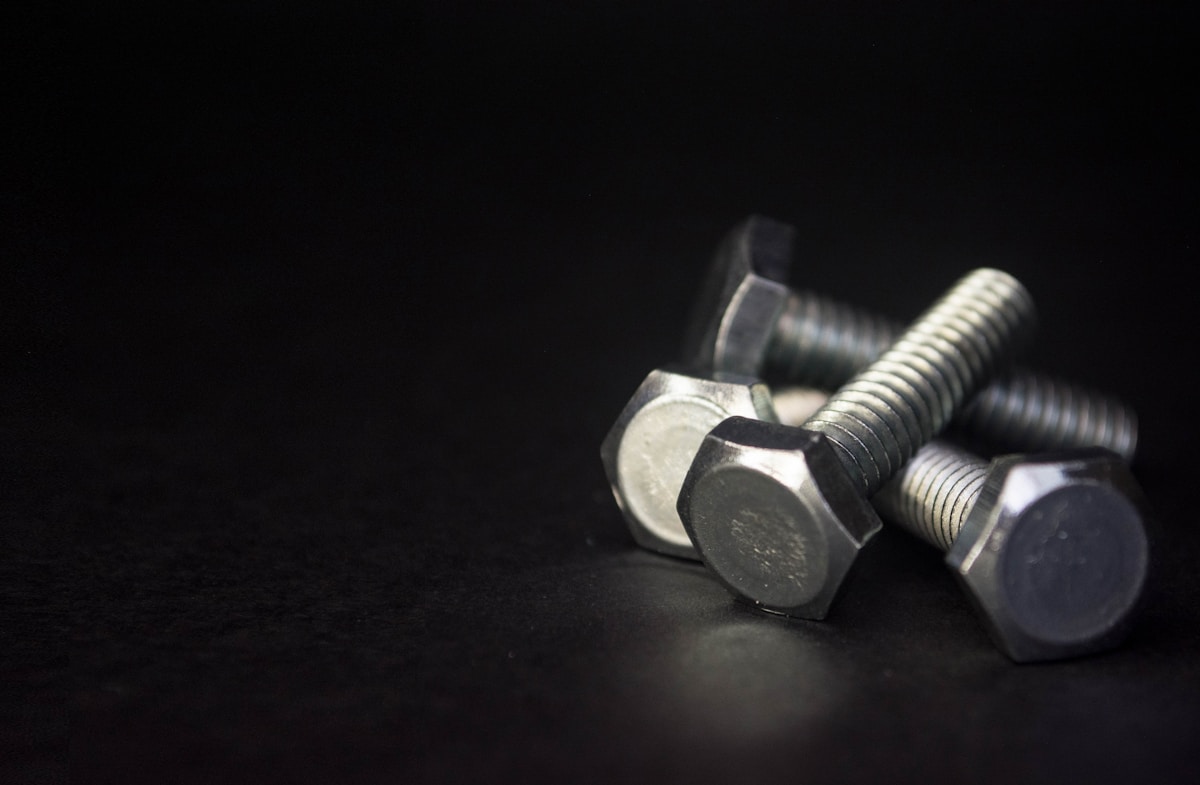
Puntos críticos de inspección
Verificación visual del acoplamiento de roscas
Mechanical integrity in helical anchors depends entirely on precise thread engagement depth, a factor often compromised by improper seating. This specific failure mode is the leading cause of premature structural fatigue, as evidenced by our field inspections across the Russian and Southeast Asian markets.
- Full Thread Penetration: The threaded rod or anchor bolt must penetrate the coupling nut until it bottoms out against the internal shoulder. If the joint remains visibly open even after the applied torque reaches the manufacturer’s specification, the assembly must be immediately rejected.
- Thread Alignment Integrity: Operators must visually confirm that the male and female threads are engaging straight-on. Any visible misalignment or “cross-threading” during the initial hand-tightening phase indicates a manufacturing tolerance failure, typically resulting in damaged pitch diameters.
- Gap Verification: Once torqued, a successful assembly should present zero gap at the coupling interface. We enforce a strict 1mm tolerance on our automated steel cross-arm production for this exact reason—ensuring that mating parts achieve full surface contact.
Estándares de detección de defectos superficiales
Surface condition is the primary indicator of long-term corrosion resistance and material homogeneity. Because we utilize hot-dip galvanizing compliant with ISO 1461 to achieve a mean coating thickness exceeding 85 microns, the surface finish must be rigorously evaluated for both galvanic defects and base-metal imperfections.
- Galvanizing Coherence: Under standard lighting, the finish should appear smooth and bright. We specifically reject any batch exhibiting bare spots, uncoated patches, or heavy zinc dross (rough, chunky buildups), as these defects expose the underlying steel to rapid environmental degradation.
- Metallic Cracks and Flaking: Due to the hot-forging process we employ rather than traditional casting, the grain structure is highly dense. Inspectors must look for hairline cracks along the bending radii or edges of guy clamps and pole bands. Furthermore, if the zinc coating flakes off during handling or impact tests, it signifies poor metallurgical bonding and immediate product failure.
- Casting/Forging Marks: While minor flash is acceptable and easily removed, deep voids, severe porosity, or cold shuts on the hardware body indicate compromised tensile strength. A 10-person QC team at our facility conducts a 100% double-review inspection to ensure every unit meets these aesthetic and structural baseline standards before packaging.
Conclusión
Strict adherence to proof-load testing protocols and material grade matching ensures structural integrity under dynamic soil stress. Matching material grades like ASTM A108 con A563 dictates ultimate tensile limits, while fatigue validation confirms performance under load. Visual thread engagement verification remains the critical first inspection step before any torque is applied to prevent premature failure.
- Consistent tensile strength is achieved by eliminating heat-affected zones through 21 years of hot-forging expertise and ISO 1461-compliant galvanizing. This process ensures durable performance in aggressive environments, exceeding ASTM A153 minimums for long-term corrosion resistance. Contact our engineering team with your specific load requirements and soil class data for a precise compatibility assessment and technical feasibility review.
Preguntas frecuentes
¿Qué es la resistencia última a la tracción?
La resistencia última a la tracción (RUT) representa el esfuerzo máximo que puede soportar un material mientras se estira o tira de él antes de formar un cuello de botella o romperse. Es una métrica crítica para pernos de anclaje, ya que indica el límite absoluto de la capacidad de carga bajo tensión axial. Los ingenieros utilizan este valor para determinar los factores de seguridad y garantizar la integridad estructural bajo cargas extremas.
¿Cuál es la diferencia entre resistencia a la fluencia y UTS?
Yield strength marks the point where a material begins to deform plastically, meaning it will not return to its original shape. Ultimate tensile strength is the maximum stress the material can endure before complete fracture occurs. For safety-critical applications like pole line hardware, engineers often design operating loads below the yield point to prevent permanent deformation.
¿El recubrimiento afecta la resistencia a la tracción?
While coatings like hot-dip galvanizing primarily provide corrosion resistance, the application process can sometimes induce hydrogen embrittlement if not properly managed. High-quality manufacturers mitigate this by baking coated bolts to remove trapped hydrogen, preserving the base metal’s integrity. When executed correctly, the coating adds negligible weight impact without compromising the bolt’s ultimate tensile strength.
¿Qué normas rigen las pruebas de anclaje?
Anchor testing is governed by international standards such as IEC, ASTM, and ISO, which define methodologies for tensile, shear, and pull-out tests. These standards specify loading rates, specimen preparation, and acceptance criteria to ensure consistent and comparable results globally. Adherence to these guidelines guarantees that hardware meets the rigorous demands of power transmission and foundation applications.
¿Puede Raxpower asistir con especificaciones personalizadas?
Yes, Raxpower offers OEM/ODM capabilities to transform specific drawings or concepts into customized pole line hardware solutions. Their engineering team can adapt dimensions, materials, and surface treatments to meet unique project requirements or regional tender standards. This flexibility ensures that clients receive tailored components that align precisely with their technical specifications.