
A disconnector at a 145 kV bay hangs its safety case on four porcelain columns. In the open position, the blades must show a visible, reliable gap; in the closed position, the same columns must hold the bus through short circuits, wind and ice. Post insulator selection for that duty is a different exercise from picking a line insulator, because the post is a structural column first and a dielectric second.
The RaxPower order desk reviews post insulator inquiries for disconnectors and substation bays every week. The recurring gap in those specifications is rigidity: cantilever ratings arrive, while deflection limits and torsion figures rarely do. This page sets out a scenario-specific method, built around the loads that disconnectors and station buses actually impose. It covers insulation levels, cantilever class, torsion and deflection, station creepage, material choice and the documents that prove the choice.
What a Disconnector Demands From Its Post Insulators
A disconnector is defined in the industry as "a mechanical switching device which provides, in the open position, an isolating distance in accordance with specified requirements". That definition loads three duty families onto the insulators underneath it. Functionally, the device must hold a visible open gap and carry normal and fault current without overheating. Mechanically, it must survive its own operating loads plus external loads. A GE Grid Solutions team writing in INMR ranks those external loads plainly: on UHV equipment, the most severe is earthquake. Short-circuit, high wind and terminal loads follow.
Environmentally, the same columns face pollution, ice and heavy rain in all weathers. Pollution is, in that INMR analysis, "a key dimensioning factor for insulators and can lead to discharge to earth". None of this is exotic; it is the everyday load map of an outdoor bay.
The disconnector adds one demand that bus supports never see: it moves. Opening and closing pushes torque and inertia reactions through the insulator column, so "a certain level of rigidity is necessary for proper function of this equipment". The same authors note the commercial stakes, because insulators account for up to 30 percent of the cost of an EHV disconnector and up to 70 percent at UHV. Poor post insulator selection therefore damages both reliability and budget at once.
Where Line Insulator Selection Rules Stop Applying
Line insulators are ropes. A suspension string is sized by tension, and a pin or Freileitungsstütc on a crossarm leans with the conductor while the structure takes the imbalance. Station posts carry their loads as if the bay were a steel building. Compression comes from the conductor above, cantilever from wind and misalignment, and, on a disconnector, torque from the operating linkage. When the same catalogue page serves both markets, the ratings that matter are simply not the same rows.
Compression is the quiet third load. A post under a riser or a vertical-break switch carries the conductor weight straight down its axis, and porcelain handles that direction well. The same unit under a horizontal pull lives a much harder life, which is why cantilever, not compression, is the published rating buyers compare. Read each data sheet for the load arrow directions before comparing numbers between suppliers.
The vocabulary shift matters when you specify. Transmission lines use line post insulators bolted to crossarms. Substations use station post insulators, the rigid units that support bus bars and switchgear while providing isolation from grounded structures. The Pfosten-Isolator-Leitfaden walks that family for overhead lines; this page concentrates on the station duty.
Selection logic follows the mechanical path. For a line, you start from conductor tension and sag. For a bay, you start from the support condition: what mass hangs on the post, and what the wind and a fault will add. The last question is how much the top may deflect before contacts misalign. Post insulator selection for disconnectors and substations therefore runs on cantilever class, torsion capacity and stiffness, with tension ratings a distant afterthought.
Start From Voltage, BIL and the Open Gap
Every specification begins with the highest voltage for equipment, written Um, because it fixes the required power-frequency and lightning impulse withstand levels. Station post classes align with IEC 60071 insulation coordination, and the standard withstand ladder for common transmission classes looks like this.
| Um (kV) | Wet power-frequency withstand (kV rms) | Lightning impulse withstand (kV peak) |
|---|---|---|
| 72.5 | 140 | 325 |
| 123 | 230 | 550 |
| 245 | 460 | 1050 |
| 420 | 630 | 1425 |
The open gap adds a second electrical requirement that pure bus supports avoid. The INMR study found that, at the stresses listed in IEC 62271-1, the distance needed between open contacts is generally lower than the distance needed to ground. Conservative practice therefore assumes the open gap must match the phase-to-earth clearance, which quietly sets a floor under insulator height for any horizontal-break switch.
The height consequence is easy to underestimate. A 145 kV disconnector needs enough column below the blade pivot to keep the open gap clear of the base steel at every tolerance. Creepage then adds on top of that. Two posts with identical impulse ratings can differ in height because of shed profile alone. Confirm the arcing distance and the creepage separately on the outline drawing, because one number does not predict the other.
At EHV and UHV, switching impulse rather than lightning dominates the dimensioning, including toward ground under rain. That is one reason very tall columns appear on high-voltage disconnectors, and why compact station designs lean on optimized post insulator profiles to trim arcing distances. Where grading control becomes marginal at those heights, a station corona ring guide covers the companion hardware.
What Each Substation Position Asks For
A bay is not one duty but several, and each mounting position weights the load set differently. Reading the position first keeps the specification honest, because a cantilever hero is rarely a torsion hero.
| Position | Dominant loads | Selection emphasis |
|---|---|---|
| Disconnector base posts | Bending plus operating torsion, terminal loads, contact alignment limits | Torsion capacity and stiffness, not just cantilever class |
| Bus support posts | Bus mass, wind, short-circuit electrodynamic forces, thermal expansion | Cantilever class, stacking plan, span coordination |
| Riser and dropper posts | Vertical compression combined with bending | Combined load check on the actual fitting |
| Equipment stands | Seismic inertia of the mounted apparatus, BIL of the stack | Seismic qualification and impulse class |
Where the posts sit is a layout question, not a component question. Span spacing, phase clearance and height optimization belong to the bus post layout guide. The two exercises still feed each other: layout fixes the loads, and selection sizes the column that takes them.
Cantilever Class: The Governing Mechanical Rating
Cantilever failing load is the headline number of any station post data sheet, and the standards make it a class system. IEC 60168 defines standard cantilever classes of 4, 6, 8, 10, 12.5, 16 and 20 kN, with a minimum design safety factor of 2.5 against the calculated working load. The working load itself is the sum of conductor pull, wind on the span, and short-circuit electromagnetic force, each applied at the terminal with its lever arm.
Porcelain technology frames the practical range. Station posts have served substations for over a century, covering 1 to 765 (800) kV. Maximum cantilever classes reach 20 to 30 kN, and single units run up to 3000 mm of length. Above 245 kV, assemblies of two or more flanged units take over. The bottom unit then carries the full cantilever moment, so it must be specified accordingly rather than assumed equal to its brothers.
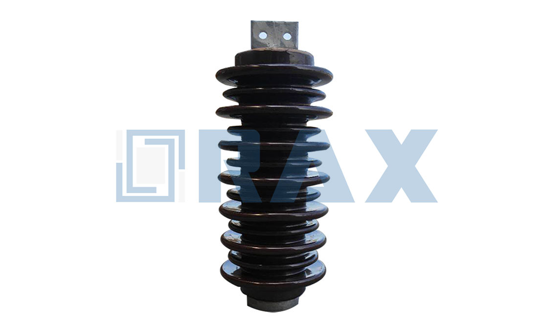
North American projects speak the ANSI dialect instead, where station posts conform to ANSI C29.9 and its TR-number classes, a line that runs from 7.5 kV up to 500 kV. Composite designs extend the mechanical ceiling: our own post insulator range lists cantilever bending strengths exceeding 40 kN, with basic impulse levels from 60 kV to over 2550 kV. Whichever dialect your tender uses, name the class explicitly, because "strong enough" is not a rating.
Torsion and Deflection: The Disconnector Premium
Here is where post insulator selection for a switch departs from post insulator selection for a bus. A center-break or rotating-knife disconnector drives its blades through the very columns it stands on. The operating mechanism therefore injects torque into the post on every single stroke. The INMR analysis names bending and torsion together as the loads that complicate insulator design for disconnectors, and no bus specification ever has to think about that second term.
Picture the blades of a center-break switch closing against a stiff winter wind. The mechanism pushes hard, the current path is still open, and every newton-meter of that effort twists the base column until the contacts meet. If the column winds up too far, the blades miss their seats, and the switch fails exactly when it is needed. The failure mode is stiffness, not strength.
Rigidity differences between materials are quantified. At the same diameter, porcelain is stiffer than composite, with a Young's modulus up to 60 percent higher. That is why GE treats displacement under load as a key design driver. The measurement is taken even though the test is classified as a special test. Composite posts answer with larger diameters, and hollow-core composite designs exist precisely to raise stiffness without a weight penalty at UHV.
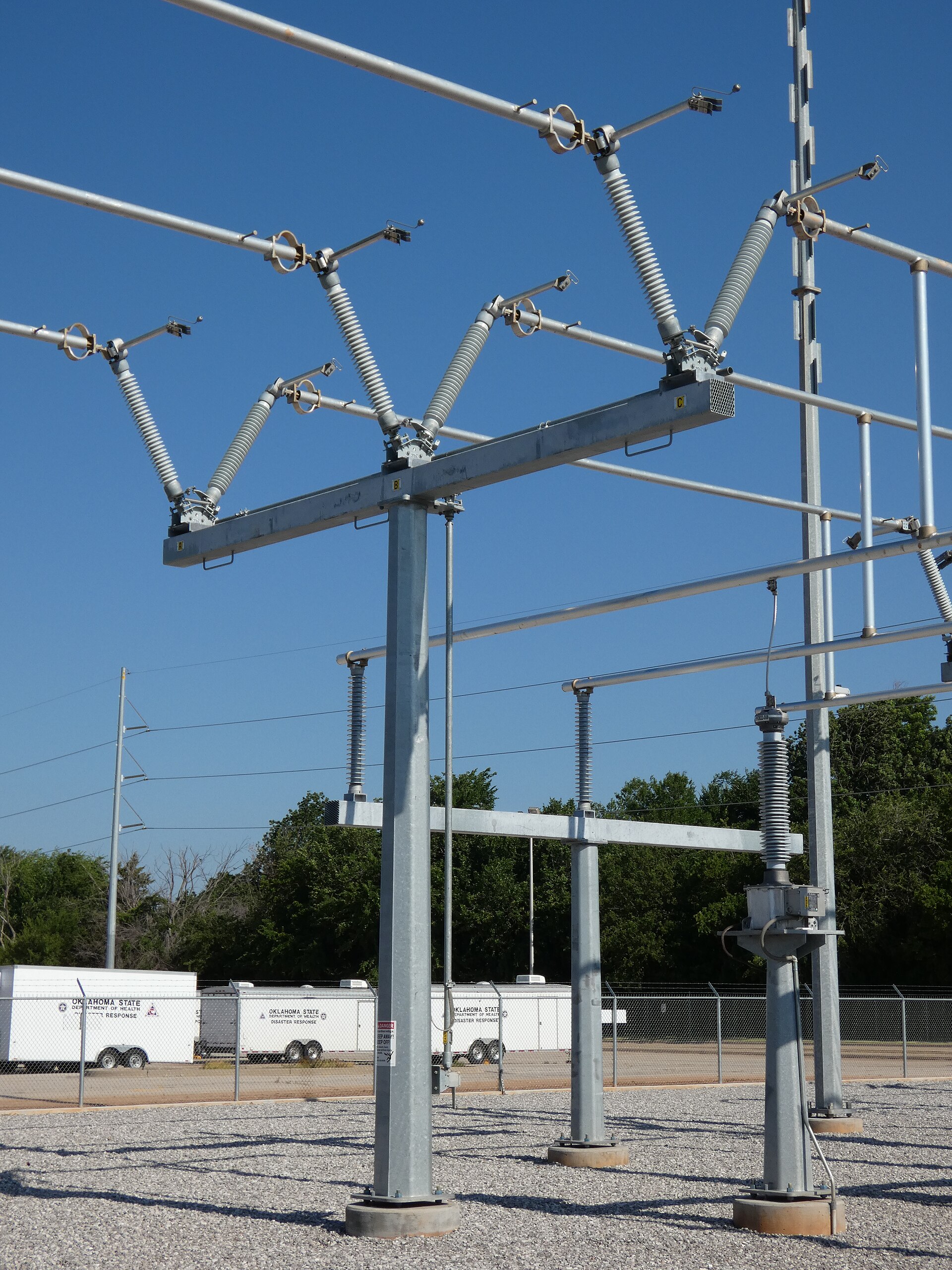
The practical specification move is simple: state a maximum permitted deflection at the terminal under the rated static terminal load, and require the displacement-under-load measurement in the test report. A 138 kV switch on its posts, as in the photograph below, makes the point visually; the columns carry both the bus pull-off and the operating torque.
Insist on the torsion figure in writing. Two posts with identical cantilever class can differ by a factor in torsional stiffness. The difference only shows up in service, as a switch that grows harder to close each season.
Pollution and Creepage at Station Severity
Stations sit beside roads, coastlines and factories, and their posts cannot be washed by swinging on a string, so creepage deserves its own chapter in any post insulator selection. IEC Technical Specification 60815 grades every site into a severity class from a, very light, to e, very heavy, and attaches a unified specific creepage distance to each class.
| SPS-Klasse | Typische Umwelt | USCD (mm/kV, phase-to-ground) |
|---|---|---|
| a | Inland rural, no industry | 22.0 |
| b | Light industry, moderate population | 27.8 |
| c | Suburban industrial, moderate coastal exposure | 34.7 |
| d | Heavy industry, near-coastal, dusty desert | 43.3 |
| e | Shoreline, severe industrial fallout | 53.7 |
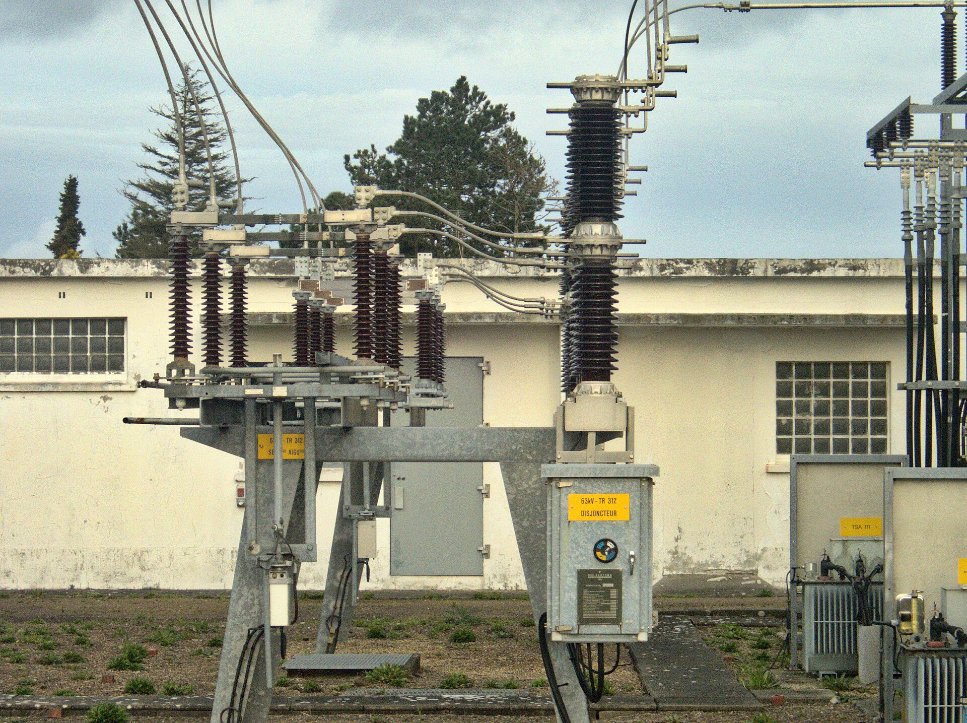
The arithmetic is direct. A 132 kV station at a heavy class d site carries 76.2 kV to ground, so the posts need about 3300 mm of creepage before any profile factors are applied. Under-specifying that number is the classic coastal substation error, and the brown glaze in the photograph below has absorbed decades of exactly such marine air.
Class evidence beats folklore. IEC 60815 assigns a site class from measured ESDD and NSDD values, collected on reference insulators over at least a year. Where measurements do not exist yet, the descriptor method substitutes. Inland desert dust, coastal salt and cement fallout land in different classes, and the class, not habit, drives the creepage number in the specification. A station post copied from a neighbouring yard inherits the neighbour's pollution, not yours.
Profile discipline keeps the creepage honest. IEC 60815 caps the creepage factor, the ratio of creepage to arcing distance, at 4 for ceramic and 4.5 for composite insulators, because deeper and deeper sheds eventually bridge underneath. Where porcelain cannot reach the required creepage within practical height, hydrophobic materials take over. The INMR review reports that hydrophobicity transfer materials can cut the required creepage by up to 30 percent. Altitude and rain bend the answer too, since withstand at 3500 m falls to roughly a third of the sea-level value, and severe rain calls for wider shed spacing. The operating playbook for polluted stations, including washing, lives in the composite insulator operation guide.
Material Choice: Porcelain, Composite, RTV or Hybrid
Five technologies compete for every station post position: solid porcelain, factory-coated porcelain, hybrid porcelain with silicone sheds, solid-core composite, and gas-filled hollow-core composite. The INMR comparison behind that list draws a clear conclusion. Solid porcelain remains the preferred and most common choice for EHV disconnectors, on cost and proven reliability. It still spans the widest voltage map, from distribution bays up to 765 kV assemblies.
Each alternative buys something specific. Factory RTV coating buys pollution performance at the price of coating maintenance, guaranteed for only about a decade. Hybrid units trim weight by only about 20 percent while costing much more than stacked porcelain, so they survive in niches. Solid-core composite posts have been on the market since the 1980s, with FRP cores of 45 to 100 mm typical diameter. They buy light weight, hydrophobicity and the best seismic dynamic behavior. That is why the material comparison guide treats them as the default upgrade path in harsh environments.
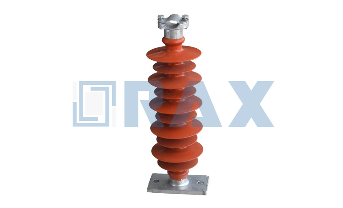
Decide by scenario, not by fashion. Inland, clean, standard service keeps porcelain ahead on price and stiffness, and the material comparison guide details the trade in both directions. Coastal, desert or heavy industrial sites push the answer toward composite or coated posts, because creepage and washing intervals dominate life-cycle cost. Seismic zones add a second vote for composite, since lower mass cuts the inertia load the post must survive. Hollow-core composite becomes competitive at UHV heights, where solid cores grow heavy and flanged porcelain stacks multiply interfaces.
Seismic and Short-Circuit Checks Before Commitment
Two transient load families can overturn an otherwise tidy selection, so check them before the purchase order, not after the first tremor or fault. For seismic duty, three qualification frameworks dominate: IEEE 693, IEC 62271-300 and ETG-1.020. They differ in load combinations and acceptance, and the INMR summary of their arithmetic is worth quoting. IEEE 693 applies seismic load alone at 100 percent in X and Y with 80 percent in Z, and demands a minimum safety factor of 2 by the SRSS combination. IEC 62271-300 instead combines the seismic case with 70 percent of the rated static terminal load and a 10 m/s wind.
Both frameworks reward the same physical recipe: a light, stiff column. Lower mass means lower inertia force, and higher natural frequency pushes the response away from the peak of the required response spectrum. Composite posts earn part of their seismic reputation here, not from strength but from weight.
Short circuits are the second overturner. Fault currents bend parallel bus posts toward each other with electrodynamic force, and that force can govern the cantilever class in high-fault substations. Compute it at the actual spacing and current, add it to wind and dead load, and only then read the cantilever table. The order matters, because post insulator selection that starts from a neat static load will quietly miss the worst case the station will ever see.
Terminal loads close the mechanical file. The rated static terminal load represents what the connected conductor or bus pushes on the terminal in normal service, and every transient case rides on top of it. Keep the request realistic. A terminal figure copied from a heavier project overfeeds the post, while a guessed one starves it. The number belongs in the data sheet, next to its direction, not buried in an email thread.

Mounting Interfaces and Bracket Stiffness
An insulator is only as stiff as the steel it stands on. The deflection budget that protects contact alignment includes the bracket, the base plate and the bolted joint, not just the column, so a soft pedestal can waste a premium insulator. Treat the support steelwork as part of the insulating system and demand its stiffness in the same breath as the post rating.
Interfaces are where mixed-vendor projects stumble. Pedestal caps, tie tops and base flanges follow standardized bolt circles and diameters, but tolerances still decide whether a stack assembles cleanly in the yard. Verify mating dimensions before delivery rather than with a wrench on site. For stacked assemblies, check flange flatness, because an angled joint at the base multiplies cantilever stress all the way up. The Säulenisolator-Halterung family and the 132 kV dimension guide cover the dimensional side in detail.
Base hardware deserves the same attention as the column. Galvanized steel base plates, correct bolt torques and flat, aligned pedestals keep the calculated load path real once the post leaves the drawing. A gap under a base plate, a re-tapped bolt circle or a shimmed corner quietly changes the moment arm and the vibration behavior. Walk the interface with the steelwork drawing in hand before the first post is set.
Horizontal mounting deserves its own line in the specification. A post laid on its side carries its own weight as a long-term bending load, sheds drain differently, and the water sits in the wrong place. Ratings assumed from vertical service do not transfer automatically, so state the orientation and let the manufacturer confirm the derating.
Tests and Documents That Prove the Choice
A station post earns trust through a short list of type tests under IEC 60168. Dry and wet power-frequency withstand prove the insulation under the two humidity extremes. Lightning impulse withstand applies fifteen positive and fifteen negative impulses at the rated class. The cantilever breaking load test loads the terminal until the unit fails, and the value must meet or clear the class. A thermal-mechanical test cycles load and temperature together to verify the cement joints, and a porosity test confirms the fired porcelain body is sealed for life.
For disconnectors, add the displacement-under-load measurement even though standards file it as a special test, because that number, not the failing load, predicts contact alignment. Composite posts bring their own battery under the composite station post standards: water diffusion, tracking and erosion, and hydrophobicity classification of the housing material.
Documents close the loop. Ask for the original type-test reports from an accredited laboratory, not summary certificates, and check that the laboratory's accreditation covers the standard you cited. Pair those with routine test values for the batch you are buying, and the file becomes the audit trail your client's engineer will actually read.
A Selection Workflow You Can Defend
Post insulator selection holds up in an audit when it runs in a fixed order, with each step closing one degree of freedom before the next opens. In our experience the sequence matters more than the software, because most bad specifications skipped a step rather than miscalculated one.
- Fix the electrical envelope: Um, the impulse class from the coordination study, and the open-gap clearance floor for every switching position.
- Classify the site: SPS class with measured or analogous ESDD evidence, plus altitude, icing and rain severity, then compute the creepage target in millimetres.
- Size the mechanical loads: cantilever from wind, terminal pull and short circuit with the 2.5 safety factor, then torsion and a deflection limit at the terminal for every moving position.
- Choose the material against the site class, seismic demand and weight limits, and record why the alternatives lost.
- Close the interfaces: end fitting type, flange patterns, stacking plan with the bottom unit sized for the full moment, and bracket stiffness included in the deflection budget.
- Demand the documents: type tests per IEC 60168 or the composite equivalent, the displacement measurement for switch posts, and batch routine tests.
By the time the inquiry leaves your desk in this shape, a supplier can quote a defensible column instead of a catalogue guess. The RaxPower engineering desk can then flag conflicts in torsion or creepage before steel is cut. That is the real payoff of disciplined post insulator selection: the switch closes smoothly for thirty years, and nobody remembers the specification meeting that made it look easy.
Häufig gestellte Fragen
Welche Lasten bestimmen die Auswahl von Stützisolatoren für einen Trennschalter?
Biegung aus Klemmen- und Windlasten, Torsion durch den Betätigungsmechanismus, Durchbiegungsgrenzen für die Kontaktausrichtung, anschließend Kurzschluss- und Erdbebenfälle. Allein die Freischalterklasse dimensioniert keinen Freischaltständer.
Warum ist eine Auslenkung an einer Trennstandarte so kritisch?
Die beweglichen Kontakte müssen bei jeder Betätigung innerhalb der Toleranzen schließen. Übermäßiger Versatz am Klemmen, nicht mangelnde Festigkeit, lässt die Klingen klemmen, daher wird der Versatz unter Last als Spezialprüfung gemessen.
Wie viel Kriechweg benötigt ein Küsten-Stützenisolator für 132 kV?
Klassifizieren Sie den Standort zunächst. Ein Standort der Klasse D bei 43,3 mm/kV benötigt bei 132 kV etwa 3300 mm Kriechstrecke, da 76,2 kV Phasen-zu-Masse multipliziert mit 43,3 mm/kV die Untergrenze festlegt.
Wann ist ein Kompositpfosten einem Porzellanpfosten überlegen?
Bei starker Verschmutzung, seismischen Anforderungen oder Gewichtsbeschränkungen, wo Hydrophobizität, geringeres Gewicht und besseres dynamisches Verhalten Vorteile bieten. Porzellan bleibt die wirtschaftliche Standardlösung für herkömmliche Umspannwerke, insbesondere im Höchstspannungsbereich.
Which standards should a station post specification cite?
IEC 60168 and IEC 60273 cover porcelain characteristics and tests, ANSI C29.9 the North American TR classes, IEC 62231 composite posts, IEC TS 60815 creepage, and IEEE 693 seismic duty.