
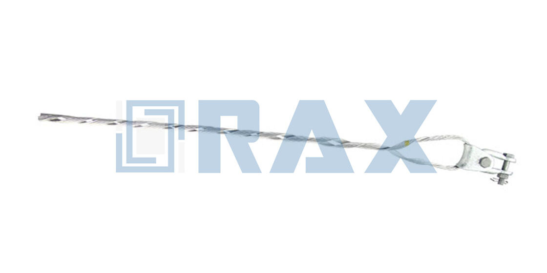
A preformed guy grip looks like a simple twisted loop. Yet every dimension on it — rod diameter, pitch, lay direction, wrap length — is engineered to match one exact strand size. When procurement teams ask how to model a preformed guy grip, they are really asking how those geometric parameters fit together. The follow-up question is whether the part arriving on site will grip the strand the way the drawing promises.
RaxPower has formed helical hardware for overhead lines since 2003, with 170+ employees manufacturing under ISO 9001. This guide breaks the modeling question into its working parts. It covers the strand the grip must match, the geometric parameters that define a grip, how the helix distributes load, and how the numbers appear in catalogs and CAD sketches.
Start From the Strand, Not the Grip
A guy grip is modeled inward from the strand it serves. Manufacturer catalogs publish grip geometry per strand size: the strand size itself, its construction (3W, 7W, or 19W wire counts), the mean diameter, and the matching grip length. One catalog example runs from a 20-inch grip for 3/16-inch strand up to a 47-inch grip for 1/2-inch strand, each with a color code for size identification.
The wire-count construction matters because it defines the strand’s outer geometry that the grip rods must wrap. Model the strand first as concentric wire layers around a core, then read the grip’s inner diameter against that finished outside diameter. Getting this order backwards — picking a grip then hoping the strand fits — is where mismatched shipments begin.
The Geometric Parameters That Define a Grip
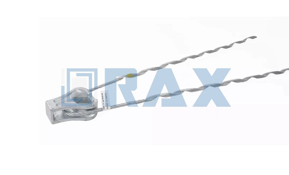
A preformed deadend specification sheet names the parameters engineers actually use: overall length, applied length, pitch length, and rod diameter. Overall length describes the part as shipped; applied length describes the grip once wrapped onto the strand, which is shorter because the helix tightens around the core.
Pitch carries the load-distribution logic. The helical rods advance a fixed axial distance per revolution, and that pitch determines how many rod turns contact each inch of strand. A grip that wraps a strand over its full applied length spreads the holding force along the strand instead of concentrating it. That is why a properly matched grip develops the full rated strength of the strand it terminates.
Applied Length and Overall Length: Two Numbers, One Grip
Specification sheets print both numbers, and the difference between them is modeling information. Overall length describes the grip as shipped, hanging open at its manufactured pitch. Applied length describes the same grip once wrapped onto its strand, when the helix has closed down onto the core. The applied figure is always the shorter of the two.
That difference gives buyers a verification tool. Wrap a sample grip on the correct strand and measure the applied length against the catalog. A close match confirms inner diameter and pitch together. A grip that closes shorter or longer than documented is wrapping the wrong strand, and no amount of torque will fix it.
Lay direction completes the model. Preformed grips are manufactured with a lay direction that must match the strand they serve. One major manufacturer builds its distribution grips for right-hand-lay conductors specifically, and its guy-strand products follow the strand standards they terminate. A left-hand strand under a right-hand grip loosens as tension rises rather than tightening. Suppliers handle both orientations, and one catalogs left-hand-lay products that pair with left-hand strands specifically. Name the strand’s lay explicitly in the specification and let the supplier match it; do not assume a default.
How the Helix Distributes Load Along the Strand
The load model answers the question every buyer eventually asks: how does a wrap of rods hold a wire without crushing it? The multiple helical legs take up tension gradually along the length of the strand, with the coils biting progressively so the grip tightens under load. Force transfer is spread across the full wrap instead of concentrating at a bolt or wedge point.
The uniform-grip principle earns its place in the model by what it prevents. A manufacturer describes its distribution grip as designed to grip the conductor uniformly and prevent distortion. That is the exact failure a bolted clamp creates at its pressure points. Where a clamp concentrates force on two contact lines, a wrapped grip carries the same tension differently. Its load spreads across dozens of small contact patches, and the strand’s wires stay in their original positions.
Material matching is part of the same model. A leading manufacturer builds its guy-grip dead-ends from the same material as the strand they are applied to and rates them at 100% of the strand’s published breaking strength. Same-material construction means the grip and strand share thermal movement and load behavior, which keeps the distribution pattern stable across temperature swings. The 100% rating also sets the failure hierarchy a designer wants: the strand itself fails before the grip slips, so nothing hangs by a partially-held wire.
The modeling principle is constant across brands: matching material, matching lay, full-length wrap.
Sketching the Helix: The CAD Basics
For drawing or verification work, CAD systems define a helix from any two of three inputs: height, pitch, and number of revolutions. Set the applied length as height and the published pitch as revolutions-per-length, and the resulting curve reproduces the grip’s rod path around the strand core.
Two modeling details keep the sketch honest. First, model the rod centerline at the rod’s mean diameter from the strand surface, not at the strand surface itself. Second, include the crossover mark. Manufacturers color-code the rod ends to identify strand size and the crossover point where application starts, and that crossover is where the model transitions to the crossed lead section.
Reading a Catalog Geometry Table Line by Line
A real catalog table shows the modeling logic in miniature. One galvanized series runs from GDE-1102 for 3/16-inch strand, a 20-inch grip coded Red. The ladder climbs through GDE-1104 for 1/4-inch strand at 25 inches in Yellow. It continues to GDE-1107 for 3/8-inch strand at 35 inches in Orange, and ends at GDE-1109 for 1/2-inch strand at 47 inches in Blue. Each row adds a construction code, 3W, 7W, or 19W, naming the wire count inside the strand.
Read across a row and the modeling chain becomes visible: strand size sets mean diameter, mean diameter sets rod inner diameter, and the required holding length sets grip length. Read down the column and the color sequence shows why installers can size a grip at a glance in the field. The table is the model, printed one row per product.
The same table answers returns and replacements. When a distributor receives a grip marked Blue for a route built on 3/8-inch strand, the color code alone identifies the mismatch. No measurement required — that is what the coding system was designed to do.
Strand Standards Close the Model at the Other End
The strand side of the model is governed by its own documents. Industry guy ends are built to develop the full rated strength of the strand under ASTM A475 grades or the CSA G12 equivalent in Canadian practice. The grip model inherits those strength definitions wholesale.
That inheritance simplifies specification work. Once the strand standard and construction are named, the rest follows. Grip geometry comes from published tables, lay direction from the strand, and the strength claim from the strand rating. Nothing in the model requires assumptions the strand datasheet does not already provide.
For galvanized steel guy wire, one manufacturer specifies Class B galvanized steel wire across every strength grade of its deadend grips. The grips work on galvanized guy wires of each strength type the standard defines. That keeps corrosion protection matched to the strand’s own finish. Material match, lay match, standard match — three confirmations that close the loop. The same three checks apply when a route mixes strand grades: each deadend grip is confirmed against its own strand, not against the strongest wire on the pole.
The catalog decides which helix mode to use. Applied length and pitch length are both printed on the specification sheet, so the height-plus-pitch mode reproduces the wrap directly from documented numbers — no derived inputs required. Sketch the strand as a cylinder at its mean diameter. Sweep the rod centerline around it at the published pitch, and the drawn wrap should land on the catalog’s applied length once the revolutions are set to match.
Application Rules That Close the Model
The geometric model ends at the application rules, because those rules are geometry in disguise. Grips are sized by strand size and construction with no measurement guesswork allowed, applied by hand to the matching strand, and color codes confirm the crossover placement. A grip applied to the wrong strand size is not a loose fit; it is a different load model entirely.
Scope matters as much as size. Manufacturers publish these grips for single wood poles in distribution construction, which tells you where the model applies and where it does not. Substation structures, transmission dead-end assemblies, and any installation needing adjustable tension belong to different hardware families with their own geometry. Reading the intended application before the geometry table keeps the model honest.
Re-use rules also trace back to geometry. One manufacturer notes its grip is intended for single use but can be reinstalled twice within 90 days. The window matters operationally. A grip removed during temporary work can go back on the same strand twice within one quarter. A grip that sat in a truck box for a season should be replaced, not reused. The same logic applies to inventory rotation: grips are boxed by size and color, and the color check at the top of the rod happens before application, not after. The manufacturer states the limit without publishing a failure mechanism, and the specification-safe reading is simply to honor it. The applied length printed in the catalog assumes first-application geometry.
In our experience, the fastest way to verify a supplier’s grip is to wrap their sample on your own strand sample and read the applied length against the catalog. If the applied length matches, the pitch and inner diameter are right; if it does not, nothing else on the datasheet matters. The tensile strength guide and the strand splice specifications cover the strength side of that verification.
Matching grips to your guy strand?
Send the strand size, construction, and lay direction, and the grip geometry comes back confirmed against the catalog before you order.

Häufig gestellte Fragen
Welche Parameter definieren eine vormontierte Stahlseilklammer?
Overall length, applied length, pitch length, and rod diameter, published per strand size and construction. Lay direction must match the strand.
Why does grip length grow with strand size?
Larger strands need more wrap contact to distribute the same-rated tension without distorting the wires, so catalogs pair each strand size with a proportionally longer grip.
Does lay direction really matter for a guy grip?
Yes. Grips are manufactured for a specific strand lay; a mismatched lay loosens under tension instead of tightening, which defeats the progressive-grip principle entirely.
Can a preformed grip be reused?
Manufacturers design them for single application, so treat the first wrap as the service configuration. At least one allows reinstallation up to twice within 90 days; the limit protects the wrap geometry the load model depends on.
How do the color codes on grip rods work?
The rod-end colors identify the strand size and mark the crossover point where application starts, so installers can confirm both size and starting position at a glance.
The Model in One Sentence
Model the strand first, then wrap the helix. The published parameters on every preformed guy grip — applied length, pitch, lay, and color code — confirm that the grip in the box is the grip on the drawing. That is the whole exercise, and it ends with hardware that holds because every variable was matched before it left the factory.