
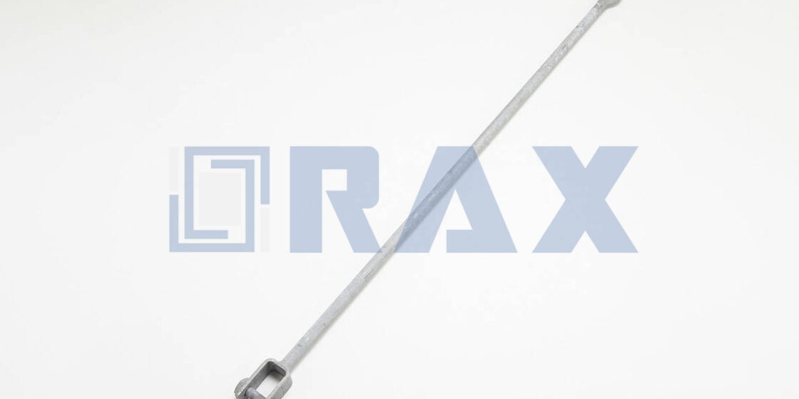
نادرًا ما تسير أعمال الأساسات الخرسانية على نحو مثالي. عندما تُصب قضبان المسامير الرابطية منخفضة جدًا بحيث لا تتشابك مع الصامولة، فإنك تجد نفسك عالقًا بين إيقاف هيكلي أو إصلاح ميداني مستعجل. دليل تصميم هيئة البناء الأمريكي (AISC) رقم 1 يحدد المشكلة لكنه يترك تفاصيل التنفيذ غامضة، مما يترك المهندسين الميدانيين للاقتران بين اللحام الميداني الخطير أو الحل الميكانيكي. الـ اقتران تمديد المسامير الرابطية يقدم مسارًا متوافقًا مع الكود للنجاة من هذا الكابوس، شريطة فهم مسار الحمل.
اختبار الشد الميداني ضد مواصفات IEC 120 يثبت أن الاقتران المُصاغ يساوي قوة الشد لقضيب الأساس، لكن تلك الضمانة تختفي بمجرد محاولة اللحام على التمديد المتعرج. نقارن المخاطر المعدنية للحام الميداني بكفاءة نقل الحمل في التوصيل الميكانيكي, ، ثم نوضح بروتوكولات التحقق المطلوبة لضمان عدم كون الاقتران هو الحلقة الأضعف في خط نقل الطاقة. ستغادر مع مواصفة واضحة لإصلاحات عالية القوة ومقاومة للتآكل تصمد في موسم الأعاصير القادم.
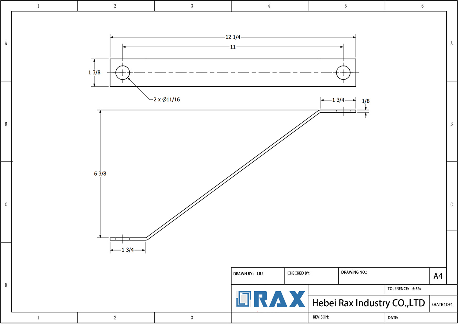
تقييم التوصيل الميكانيكي مقابل تمديدات اللحام
يقدم اللحام الميداني لقضبان المسامير الرابطية مناطق متأثرة بالحرارة تُضعف السلامة الهيكلية، بينما يحافظ التوصيل الميكانيكي على الاتساق المعدني ويضمن نقل حمل موثوق. بالنسبة لمقاولي المرافق، فإن تجنب التعديلات الحرارية يقضي على فشل الانكسار الكارثي في المناخات القاسية.
مخاطر التدهور المعدني أثناء عمليات اللحام الميدانية
عندما يحاول عمال الخطوط تعديل قضبان المسامير الرابطية أو التمديدات في الموقع باستخدام لحام القوس أو MIG، فإنهم يغيرون في الأساس الأساس المعدني للفولاذ. الحرارة المركزة الموضعية تخلق heat-affected zone that cools unevenly, resulting in brittle grain structures that cannot withstand the constant dynamic tension of guy wires. Our engineering team consistently finds that these thermal modifications become the weakest link long before the base metal yields, especially when subjected to freeze-thaw cycles or seismic activity. Mechanical threading bypasses this vulnerability entirely by maintaining the original forged grain alignment, ensuring the component behaves predictably under sudden shock loads rather than snapping without warning.
كفاءة نقل الحمل في اقترانات التمديد المتعرجة
The primary failure point in extension systems is almost always inefficient load distribution across the connection interface. Welded joints force stress concentrations into microscopic irregularities along the fusion line, which accelerates fatigue cracking. Threaded mechanical couplers solve this by utilizing precision-cut threads that ensure uniform stress distribution across the entire cross-section. We design our couplers to engage exactly where the steel is most robust, eliminating the guesswork of field fit-ups. This engineered tolerance means that during installation, foremen do not need to rely on welder skill levels to guarantee structural continuity. Every connection transfers tension linearly, drastically reducing the risk of catastrophic thread stripping or bolt shear during peak wind events.
توافق الجلفنة والحفاظ على سماكة الطلاء
Preserving the zinc barrier is not just a maintenance preference; it is a non-negotiable requirement for underground infrastructure longevity. The intense thermal output required for welding inevitably burns through protective galvanization, exposing bare steel to electrochemical corrosion the moment the trench is backfilled. Once that barrier is breached, rust propagation spreads rapidly along the grain boundaries, compromising tensile strength long before the anchor is pulled. By selecting pre-galvanized mechanical splices, utilities maintain a continuous corrosion-resistant envelope around the entire assembly. Our production standards strictly enforce coating adhesion protocols to prevent flaking during transport and handling, guaranteeing that the hardware survives decades of exposure to aggressive soil pH levels and heavy groundwater fluctuation across demanding regional tenders.
| معلمة | Mechanical Splicing | Welding Extensions | Engineering Impact | Standard Compliance |
|---|---|---|---|---|
| عملية التصنيع | Hot-forging eliminates internal casting voids | Fusion creates heat-affected zones altering grain structure | Forged consistency ensures precise dimensional tolerances | Compliant with ISO 1461 and IEC 120 testing protocols |
| Tensile Yield Strength | Delivers 30% higher yield than cast alternatives | Variable strength dependent on filler metal and technique | Prevents catastrophic snap failures under extreme dynamic loads | Meets high-breaking load requirements for Russia and South America |
| الحماية من التآكل | Uniform hot-dip galvanizing exceeds 85-micron thickness | Thermal damage at joints necessitates manual touch-up repairs | Eliminates rust-out risks in the critical soil dip zone | Strictly adheres to ASTM A153 and ISO 1461 coating specs |
| Installation & Torque Management | Engineered torque ranges prevent thread stripping | Requires specialized field labor and extended curing periods | Reduces installation errors and accelerates utility deployment | Optimized for Southeast Asia regional tender specifications |
| Quality Control & Verification | 100% dual-inspection by dedicated 10-person QC team | Relies on destructive sampling and radiographic checks | Guarantees structural integrity without production delays | Fully SGS verified for global infrastructure export |
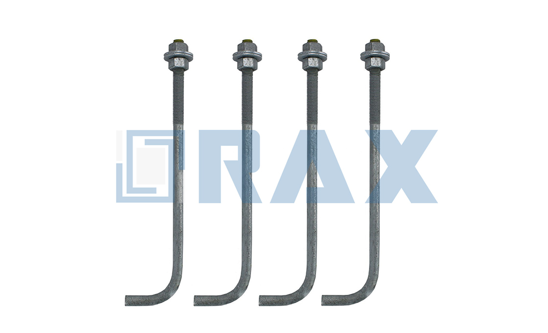
آثار سعة الحمل والصلابة الهيكلية
Structural integrity in overhead line hardware depends on ensuring coupling assemblies match or exceed the yield and tensile strength of the parent anchor rod, preventing connection failures under dynamic environmental loading.
تكافؤ قوة تجميع الاقتران
The most common structural failure in utility installations occurs when the coupling assembly becomes the weakest point in the anchor rod system. Engineering standards mandate that coupling assemblies must meet or exceed the minimum yield and ultimate tensile strength ratings of the original anchor rod. When a splice or extension fails to maintain this strength parity, cumulative stress concentrations develop at the connection interface during wind sway or ice accretion events. Proper engineering requires matching grade specifications across all threaded and forged components to distribute axial loads evenly.
- Yield Strength Threshold: Coupling assemblies must sustain initial plastic deformation at loads equal to or greater than the parent rod specification to prevent permanent elongation under peak utility tensions.
- Ultimate Tensile Capacity: Final fracture resistance of the connection hardware must align with standardized safety margins defined by regional grid codes.
- Stress Concentration Mitigation: Geometric transitions at coupling shoulders must be engineered to eliminate sharp radius changes that initiate fatigue cracks under cyclic loading.
عمليات التصنيع وسلامة البنية الحبيبية
The method used to form pole line hardware directly dictates its load-bearing capabilities. Traditional casting processes introduce microscopic porosity and inconsistent grain boundaries that significantly reduce tensile performance. In contrast, hot-forging compresses the metal matrix, aligning the grain structure along the axis of maximum stress. This directional grain flow substantially increases breaking loads and fatigue resistance, making forged hardware the standard for critical anchor rod extensions and high-tension fasteners.
Automated production lines further stabilize these mechanical properties by maintaining strict dimensional control throughout the forming process. Consistent dimensional accuracy prevents uneven load distribution across bearing surfaces and threaded interfaces. Even minor deviations can shift stress profiles away from designed load paths, accelerating wear in utility-grade applications.
- Forged Grain Alignment: Provides superior directional strength compared to cast equivalents, directly improving breaking load ratings.
- Precision Tolerance Control: Automated machining maintains strict dimensional tolerances (±1mm) to ensure uniform load transfer across coupling faces.
- Surface Finish Consistency: Smooth, bright finishes resulting from controlled forming processes minimize stress risers before secondary treatments are applied.
الأحمال البيئية ومتطلبات المواصفات الإقليمية
Structural integrity requirements scale according to regional environmental stressors. Utility procurement standards vary significantly based on geographic loading conditions. Markets experiencing heavy ice accumulation and extreme cold temperatures require hardware rated for substantially higher breaking loads to withstand combined static and dynamic forces. Conversely, regions with high seismic activity or frequent cyclonic winds prioritize fatigue resistance and cyclic load performance over absolute maximum pull-out strength.
Testing protocols verify these specifications under controlled laboratory conditions. Rigorous load testing procedures, conducted in accordance with established international standards such as IEC 120, validate that production batches consistently deliver the rated mechanical performance. These tests confirm that theoretical calculations translate into reliable field performance, ensuring that structural capacity remains predictable across all installation environments.
- Extreme Climate Ratings: High-breaking load specifications are mandatory for utility networks operating in severe winter conditions to prevent structural collapse under ice loading.
- Cyclic Fatigue Validation: Repeated load testing confirms long-term durability in regions subject to constant wind vibration or seismic movement.
- Batch Consistency Verification: Standardized testing protocols ensure that every manufactured unit meets the exact mechanical thresholds required by regional grid operators.

توافق المواد ومقاومة التآكل
Material incompatibility and insufficient coating thickness are the leading causes of premature failure in pole line hardware. Ensuring strict adherence to ISO 1461 and managing galvanic potential between dissimilar metals are non-negotiable for long-term infrastructure integrity.
In overhead line and anchoring systems, material compatibility is the primary determinant of service life, particularly when components operate in corrosive environments such as industrial zones or high-moisture soils. The most critical technical challenge is preventing galvanic corrosion, an electrochemical process that occurs when dissimilar metals are electrically connected in the presence of an electrolyte. For utility hardware, this often manifests when copper grounding conductors or brass attachments are coupled with carbon steel crossarms or anchor rods. If the steel is anodic relative to the connected metal, it will corrode sacrificially, leading to rapid structural degradation of the primary load-bearing member.
معايير الجلفنة الساخنة وسلامة الطلاء
While general steel grades provide tensile strength, they lack inherent corrosion resistance. Therefore, the protective coating acts as the primary barrier against oxidation. For pole line hardware and earth anchors, hot-dip galvanizing is the industry benchmark, surpassing electroplating in durability and abrasion resistance. Compliance with ISO 1461 is essential, requiring a mean coating thickness exceeding 85 microns. This thickness ensures that the zinc layer can withstand the abrasion of soil particles during installation and the chemical attack of soil acidity over decades of service.
- ISO 1461 Compliance: Ensures a uniform, metallurgically bonded zinc layer that provides both barrier and cathodic protection to the base steel.
- Coating Thickness: A mean thickness exceeding 85 microns is critical for extending service life in aggressive soil conditions, significantly reducing the maintenance frequency of utility poles.
- ASTM A153 Standard: For forged hardware like anchor rod extensions and couplers, adherence to ASTM A153 Class C specifications is standard to ensure coating weight and uniformity on irregular surfaces.
Be wary of “cold galvanizing” or spray-on zinc repairs for field cuts. These do not offer the cathodic protection of hot-dip galvanizing. Any field modification exposing bare steel must be treated with a zinc-rich paint containing a minimum of 92% zinc dust by weight in the dry film to approximate the galvanic protection of the original coating.
تعارض الطلاء مع ملائمة التعرجات
A major sourcing pitfall involves the conflict between corrosion protection and dimensional tolerance. Achieving a zinc coating thickness of over 85 microns naturally adds material to the surface of the component. On threaded anchor rod extensions or couplers, this buildup can change the effective pitch diameter of the threads. If the galvanizing process is not controlled or the threads are not re-chased (tapped) after galvanizing, the male and female threads will seize during installation. This often forces installation crews to run a die over the threads in the field, stripping away the critical zinc layer and creating an immediate corrosion point.
High-quality manufacturing mitigates this through precise gauge testing per IEC standards. By strictly monitoring the galvanizing bath temperature and dip duration, manufacturers can control the zinc alloy layer formation. Furthermore, advanced facilities utilize automated or semi-controlled tapping processes to clear threads of excess zinc without exposing the base steel, ensuring that the corrosion protection remains intact while maintaining a strict tolerance fit for mechanical splicing.
التوافق الجلفاني في التجمعات المعدنية المختلفة
For utility applications requiring mixed materials, such as attaching stainless steel hardware to galvanized steel crossarms, isolation is mandatory. Direct contact between stainless steel (cathodic) and galvanized steel (anodic) can accelerate the corrosion of the zinc layer. To prevent this, engineers must specify non-conductive separators, such as neoprene or polyethylene gaskets and washers, at the interface points. This isolation breaks the electrolytic path, preserving the galvanic coating on the structural hardware and ensuring the system meets its design life requirements without premature failure due to galvanic corrosion.
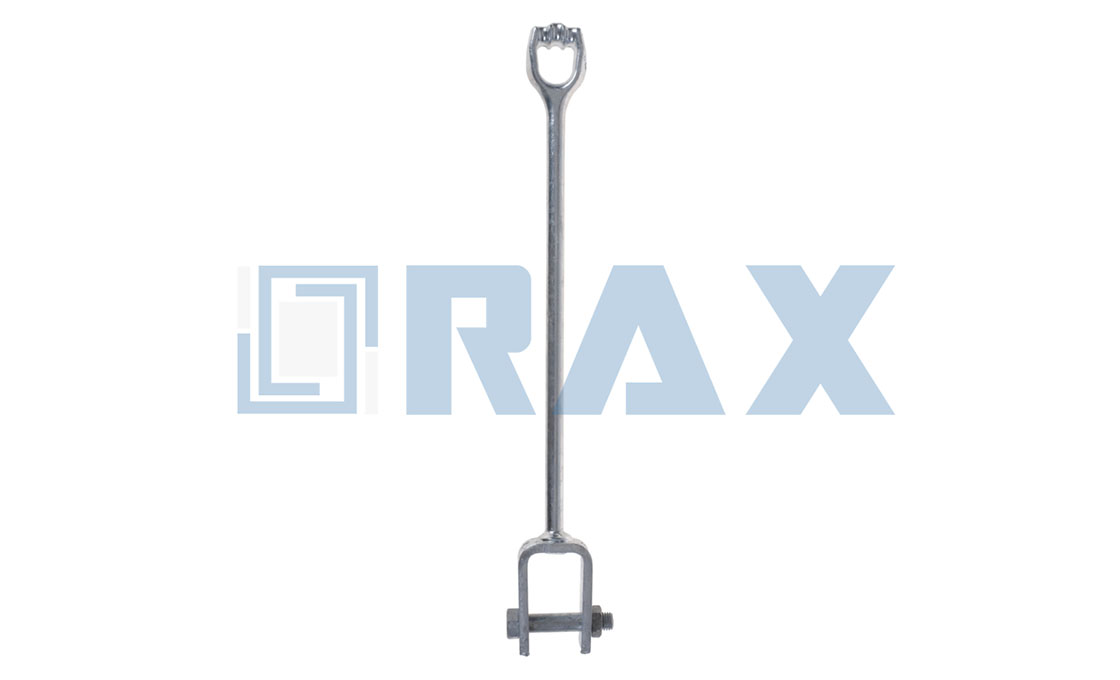
معايير الاختيار بناءً على المادة الأساسية والطول
Selecting the correct anchor rod extension requires exact thread matching (pitch and diameter) to the existing substrate and precise length calculation based on baseplate geometry to avoid expensive rework.
توافق مواصفات التعرجات
The primary failure mode in anchor rod extensions is thread mismatch, often caused by confusion between Unified National Coarse (UNC) and Metric standards. A nominal diameter of 25mm does not guarantee compatibility with a 1-inch rod. Procurement teams must verify the Threads Per Inch (TPI) or pitch explicitly on the engineering drawings. For utility poles, UNC threads (e.g., 1″-8 UNC) are common in legacy North American infrastructure, while Metric threads (e.g., M24 x 3.0) dominate in Asian and European specifications. Mixing these creates a “cross-threading” scenario that compromises the tensile integrity of the entire pole line foundation.
Furthermore, the galvanizing thickness significantly impacts thread fit. High-quality hot-dip galvanizing, compliant with ISO 1461, adds a mean coating thickness often exceeding 85 microns to the steel surface. This buildup can alter the effective pitch diameter. Standard coupling nuts designed for black steel may not fit over galvanized extensions without stripping the coating. Therefore, extensions and couplers must be “oversized tapped” or galvanized together as a matched set to ensure full thread engagement without forcing the connection.
حساب الشكل الهندسي والطول
Determining the correct extension length is not merely about reaching the top of the baseplate; it requires accounting for the full stack-up of hardware and concrete tolerances. The calculation must include the baseplate thickness, the height of the leveling nut (if used), the thickness of the nut and washer on top, and the required “stick-up” beyond the nut for safety and future adjustment. For automated manufacturing contexts, maintaining a strict tolerance (e.g., ±1mm) on the cut length of these extensions is critical to ensure they do not bottom out in the coupler before reaching the required torque.
Concrete edge distance also influences selection, particularly when extensions are used to rectify foundation setbacks. If an extension is used to offset a rod that was placed too close to the concrete edge during the pour, the bending moment on the extension increases significantly as the lever arm extends. Engineers must verify that the new effective length, combined with the baseplate geometry, does not violate the minimum concrete edge distance required to prevent side-face blowout. The extension effectively moves the critical failure plane up the rod, which must be evaluated against the concrete’s compressive strength.
- Baseplate Stack-Up Calculation: Total Extension Length = (Grout/Leveling Pad Gap) + (Baseplate Thickness) + (Top Nut Height) + (Washer Thickness) + (Minimum Stick-up of 1.5x Thread Pitch).
- Coupler Engagement Check: Ensure the extension length allows for a minimum engagement depth of at least 1.0 times the nominal diameter (e.g., 25mm engagement for a 25mm rod) within the coupler to develop full tensile strength.
- Galvanizing Allowance: If the extension is threaded after galvanizing, the diameter is reduced. If galvanized after threading, the diameter is increased. The selection must match the processing method of the existing substrate rod to avoid assembly issues.
📋 قائمة التحقق
- Step 1: Verify the substrate thread type (UNC vs. Metric) using a thread pitch gauge. Do not rely on visual inspection.
- Step 2: Measure the total “projection length” required from the concrete surface to the top of the nut.
- Step 3: Confirm the coupler length is sufficient to accommodate the extension rod’s engagement plus the existing rod’s engagement simultaneously.
- Step 4: Check that the extension steel grade matches or exceeds the substrate (e.g., ASTM A36 or A193 Grade B7).

متطلبات عزم الالتفاف والمسافة وعمق التضمين
النقاط الرئيسية
- Installation torque must be precisely calibrated to induce optimal clamping force without exceeding the yield strength of the anchor rod.
- Thread engagement depth in extension couplers is critical; insufficient engagement strips threads and creates catastrophic failure points under tension.
- Hardware spacing and embedment depth are interdependent variables that dictate load distribution across the pole structure and soil holding capacity.
تحسين قوة التشدد ومشاركة التعرجات
The primary objective of applying specific torque to anchor rod extensions is to generate a predictable clamping force that secures the hardware against the pole surface while pre-loading the assembly. In utility applications, this relationship is governed by friction and material stiffness. If the applied torque is too low, vibration and wind loads can cause gradual relaxation of the hardware, leading to structural movement. Conversely, excessive torque induces torsional stress that can exceed the yield point of the steel, potentially causing thread stripping or permanent deformation of the rod.
For anchor rod extensions utilizing threaded couplers, the depth of thread engagement is a non-negotiable parameter for maintaining tensile integrity. Industry standards typically require a minimum engagement depth equivalent to or greater than the nominal diameter of the rod to ensure that the full tensile strength of the rod is developed before the threads fail. When installing forged extension couplers, it is imperative to ensure that the male and female threads are fully seated. Any gap reduces the effective shear area of the threads, significantly lowering the assembly’s overall breaking strength. Installers must verify that the rotation continues until the threads are bottomed out or achieve the specified engagement length, ensuring the tension path is unbroken.
تباعد الأدوات الاستراتيجي لحماية سلامة القطب
Hardware spacing is not merely a matter of convenience; it is a critical factor in preserving the structural cross-section of the utility pole. When anchor brackets or guy wire attachments are clustered too closely, the compressive forces exerted by the hardware overlap, creating a localized stress zone that can exceed the bearing capacity of the material. In wooden poles, inadequate spacing can cause crushing of the wood fibers or longitudinal splitting along the grain, effectively destroying the pole’s ability to resist bending moments. For steel or concrete poles, improper spacing can induce fatigue cracks or spalling.
Proper spacing ensures that the load from the anchor is distributed over a sufficient area of the pole, keeping the induced stresses well below the elastic limit of the pole material. This spacing must be calculated in relation to the circumference of the pole and the diameter of the hardware. By maintaining uniform intervals, installers prevent the “crowding” effect that acts as a stress riser, thereby ensuring the long-term stability of the anchor attachment point and the structural longevity of the pole itself.
عمق التضمين وميكانيكا التربة
The holding capacity of an earth anchor is fundamentally derived from the shear strength of the soil mass located above the anchor’s helix or bearing plate. therefore, embedment depth is the single most influential variable in determining an anchor’s resistance to pull-out. The depth of installation must be sufficient to penetrate beyond the active soil zone—the upper layer of soil subject to seasonal moisture variation, freeze-thaw cycles, and erosion. Anchors installed within this active zone are prone to “heave” during frost events or loss of grip during heavy saturation, resulting in immediate failure of the guyed structure.
Determining the correct embedment requires an understanding of the soil class. Loose sandy soils or cohesive clays exhibit different shear properties, meaning an anchor in loose soil must be driven deeper to achieve the same holding capacity as one in dense gravel. The installation depth must ensure that the helix or plate engages a stable soil stratum that can provide the necessary reaction force. additionally, deep embedment ensures that the failure cone—the inverted cone of soil that would theoretically be pulled out during a failure event—is large enough to mobilize the weight and shear strength of the soil required to counteract the maximum design loads of the transmission line.
| معلمة | المواصفات | Requirement | الميزة |
|---|---|---|---|
| Anchor Rod Torque | Shaft diameter directly determines the required installation torque specifications. Torque requirements are 400 ft-lbs for 3/4-inch shafts, scaling to 2300 ft-lbs for 1.25-inch variants. | Apply calibrated torque wrench; avoid over-tightening to prevent thread stripping | Ensures optimal tension transfer without compromising hot-forged structural integrity |
| Hardware Spacing | 12–24 inch intervals per regional utility standard | Maintain uniform load distribution across wooden or composite poles | Prevents localized stress fractures and ensures consistent structural alignment |
| Earth Anchor Embedment Depth | 6–10 feet depending on soil class and design wind load | Install below active frost line; ensure helical plates engage stable soil strata | Maximizes holding capacity for extreme environmental conditions and high-breaking loads |
| الحماية من التآكل | ISO 1461 Hot-Dip Galvanizing (>85 microns mean thickness) | Ensure full submersion coverage for complete underground dip-zone exposure | Eliminates rust-out risks and provides superior longevity compared to thin coatings |
| Load Testing & Verification | IEC 120 compliant load testing + 100% double-review inspection | Conduct in-house gauge testing prior to packaging; maintain SGS third-party records | Guarantees zero casting voids and delivers 30% higher tensile yield than cast alternatives |

الامتثال لمواصفات الهندسة ومعايير الاختبار
High-voltage infrastructure demands strict adherence to material coating standards (ISO 1461), manufacturing precision (1mm tolerance), and load testing protocols (IEC 120) to ensure structural longevity.
معايير الجلفنة: ASTM A153 و ISO 1461
Corrosion resistance is the primary defense against failure in overhead line hardware. While ASTM A153 provides the classification for zinc-coated iron and steel hardware—specifying coating classes based on material thickness—ISO 1461 sets the global benchmark for the hot-dip galvanizing process itself. For components operating in high-corrosion environments or demanding utility markets, a mean coating thickness exceeding 85 microns is increasingly considered the industry standard for premium reliability. This level of protection significantly surpasses the minimum requirements for standard commercial applications, ensuring that anchor rods and extensions maintain structural integrity over decades of exposure to harsh elements.
اختبار الحمل والامتثال الأبعادي
Ensuring fit and function requires rigorous validation against international testing protocols. Dimensional accuracy is frequently verified using gauge testing compliant with IEC 120 standards, which guarantees that threads and diameters adhere to strict tolerances—often within 1mm for precision components like steel crossarms. Beyond dimensional checks, hardware must undergo thorough load testing to evaluate its performance under stress. This includes:
- Proof Load Testing: Verifying that the hardware can withstand a specified load above the rated working load without permanent deformation.
- Tensile and Break Load Testing: Determining the maximum axial load the material can sustain before failure, critical for anchor rod extensions.
- Seismic and ICC-ES Compliance: For projects in regulated markets, components may need to meet ICC-ES acceptance criteria (AC158) for anchor strength in cracked concrete or specific soil conditions.
When evaluating technical data sheets, do not accept generic “tested” claims. Demand specific test report references that cite ASTM أو IEC standards by revision number (e.g., IEC 120:1977). Verify that the proof load values listed match or exceed the safety factors (typically 2:1 or 5:1) required by your local utility code.
التحقق العالمي والشهادات
Navigating the procurement environment for utility hardware requires validation from independent third-party bodies. Compliance with international tender specifications—particularly in markets like South America or Southeast Asia—often necessitates certification from globally recognized agencies. Verification by entities such as SGS confirms that materials meet specific chemical composition requirements and that finished products adhere to mechanical property standards like yield strength and elongation. For B2B buyers, requiring third-party verification acts as a critical quality gate, ensuring that the delivered products align strictly with the engineering specifications approved during the design phase.
بروتوكولات التحقق الميداني وضمان الجودة
Field verification for pole line hardware relies on strict torque calibration, precision dimensional gauging, and standardized tension testing to prevent structural failures under grid load.
متطلبات معايرة عزم الالتفاف لتثبيت كم التوصيل
Splice sleeve failure rarely stems from material weakness; it almost always traces back to improper installation tension. During field verification, every torque wrench must be calibrated to an accuracy of ±3% before deployment. Rax Power’s hot-forged sleeves and fasteners are machined to minimize friction variance, which means installation torque can be applied consistently without risking thread stripping or clamp slippage. We mandate that site supervisors verify torque tool certification logs prior to crew dispatch, ensuring that mechanical readings never drift outside factory specifications.
- Calibration Frequency: Torque instruments must be re-verified every 500 actuations or monthly, whichever comes first.
- Application Protocol: Apply torque in a cross-pattern sequence to distribute mechanical stress evenly across the splice interface.
- Friction Compensation: Adjust baseline torque values by ±10% if zinc spall or surface roughness exceeds standard hot-dip galvanized finishes.
التحقق من التسامحات الأبعادية باستخدام أدوات قياس دقيقة
Manufacturing consistency is meaningless if field measurements drift outside acceptable engineering limits. Verification requires digital calipers and thread pitch gauges capable of measuring to 0.02 mm resolution. While many competitors rely on post-production sampling, we enforce a double-review process where 100% of batches are checked against master tolerance charts before leaving our facility. In the field, inspectors should measure bolt diameters, groove widths, and anchoring bore sizes before mounting. Any component deviating more than 0.5 mm from the specified dimension must be quarantined immediately. Hot-forging eliminates internal porosity and ensures that geometric dimensions hold under extreme thermal cycling, which is why our hardware consistently passes rapid dimension checks without requiring aftermarket machining.
Precision gauging also prevents assembly interference when pairing our hardware with third-party insulators or suspension clamps. By cross-referencing field measurements against the original mill certificates, contractors can guarantee that load paths remain unbroken. We recommend storing calibration tools in temperature-controlled cases to prevent thermal expansion from skewing micrometer readings during high-humidity field conditions.
اختبار الشد الميداني ضد مواصفات IEC 120
Theoretical load ratings only prove their worth when validated under physical stress. IEC 120 mandates specific load application rates, holding durations, and failure thresholds for overhead line accessories. Field technicians conducting pull tests must use hydraulic jacks rated for continuous pressure maintenance, not intermittent pumping. We require test setups to mimic actual grid conditions by applying axial tension at a controlled rate of 5 kN per minute until reaching 80% of the stated breaking load.
- Loading Rate: Maintain steady hydraulic pressure at 5 kN/min to prevent impact shock on forged joints.
- Dwell Duration: Hold peak load for 60 seconds while monitoring for micro-slip or coating delamination.
- Pass/Fail Criteria: Components must sustain 100% of rated working load without permanent deformation exceeding 0.1% strain.
Our dedicated quality control team subjects every production run to identical parameters, verifying that hot-dip galvanized components exceed 85 microns in coating thickness while maintaining tensile yield strength. If a field sample shows micro-fracturing at the splice point before reaching 75% of rated capacity, the batch is rejected. This strict adherence to IEC 120 parameters ensures that utility infrastructure withstands decades of wind sway, ice loading, and thermal expansion without compromise.
الخلاصة
Mechanical splicing beats field welding every time. Arc heat degrades the base rod metallurgy. Threaded couplers transfer load predictably without reheating the steel. Galvanizing thickness remains intact when you skip the torch. Your holding capacity math fails if you ignore torque specs matched to soil class ratings. IEC 120 tension testing exposes dimensional tolerance drift before the assembly reaches the foundation.
- Calibrate dial wrenches to the exact splice sleeve specifications before installation.
- Execute IEC 120 pull tests on random samples from each production lot.
- Forward your substrate density and embedment depth targets to our engineering team for a complimentary structural review.
عازل مثبت على العمود يمسك بالمواسير الرأسية على مسافة ثابتة من سطح العمود، مما يحمي الكابلات ويحافظ على الفصل عن الموصلات والمعدات الأخرى.
هل جميع تعرجات المسامير الرابطية موحدة؟
على خلاف الافتراضات الشائعة، لا تتبع جميع خيوط قضبان المرساة مواصفات موحدة. تستخدم العديد من المسامير الأساسية المخروطية خطافات (pitch) خاصة أو غير قياسية تتطلب موصلات أو اقترانات متخصصة. إن التحقق من خطوة الخيط والقطر قبل شراء التمديدات يمنع التعديلات الميدانية باهظة التكلفة ويضمن تفاعلاً ميكانيكياً آمناً.
كيف تُصلح رفع المسامير الخاطئ؟
When anchor bolts are set too low during concrete placement, mechanical extension couplings provide a reliable field solution. These couplers thread directly onto the exposed rod, restoring the required height without compromising structural integrity. Proper alignment and torque application ensure the extended section performs identically to the original foundation bolt.
هل يمكن لحام مسامير F1554 بأمان؟
Weldability depends heavily on the specific ASTM F1554 grade and carbon equivalent values. Grade 36 generally offers good weldability with standard preheat procedures, while Grade 55 requires stricter controls to prevent hydrogen cracking. Engineers should always consult welding procedure specifications and perform qualified tests before joining these rods to base plates.