
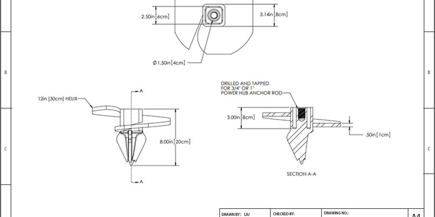
يؤدي فشل سلك داعم واحد إلى إنزال برج نقل، ويكون السبب الجذري في معظم الأحيان هو المرساة. يمكنك تحديد أقوى معدات القطب المتاحة، ولكن إذا تحرك الأساس في التربة، سيفشل الهيكل بأكمله. اختر المرساة اللفلية للخدمات تتطلب مطابقة تصميم اللولb مع ميكانيكا التربة بدلاً من اختيار عنصر قياسي من الكتالوج. تظهر بيانات التصنيع لدينا أن متوسط سماكة طلاء الجلفنة الذي يتجاوز 85 ميكرون ضروري لاجتياز التحقق من مطابقة ASTM A153 الفئة C في البيئات المسببة للتآكل، ومع ذلك فإن العديد من المواصفات القياسية لا تصل إلى هذا الحد.
يُعد تحديد نوع المرساة الخاطئ سبباً في تحويل التركيب الاعتيادي إلى تأخير في المسار الحرج. يوضح هذا الدليل الفروق الهندسية بين تصاميم عديمة المفتاح ووحدة القدرة لمساعدتك في مطابقة القدرة التحملية لتضاريسك. نغطي أيضاً متطلبات عزم الدوران لـ تصنيفات التربة والبروتوكولات الصارمة للتحقق من الأحمال اللازمة للوفاء بـ معايير IEC دون المساس بجداول التسليم.
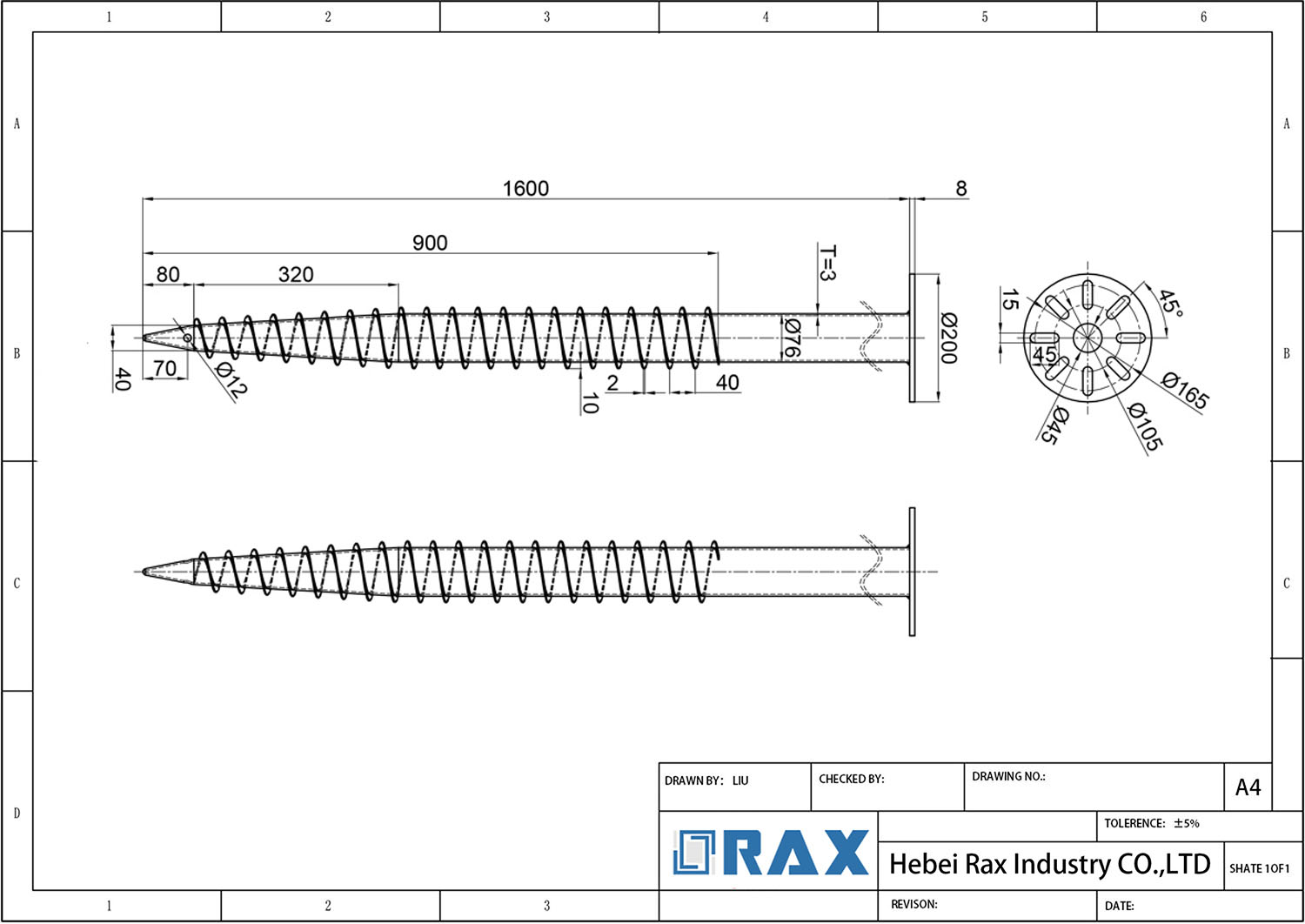
أنواع مراسي الخدمات اللفلية
Selecting the correct utility screw anchor type dictates structural longevity, directly mapping soil mechanics to expected load profiles.
الفرق بين النوع اللولبي وعديم المفتاح ووحدة القدرة
Helical screw anchors rely on engineered bearing plates to convert rotational torque into vertical uplift resistance. They excel in cohesive clay and firm substrates where soil displacement creates a permanent mechanical lock around the shaft.
مراسي البراغي بلا مفتاح strip away complex plate configurations in favor of rapid deployment. Their simplified tip geometry allows manual or basic rotary insertion, making them ideal for temporary guy wires or low-tension utility bracing where installation speed outweighs maximum holding capacity.
Power hub anchors integrate a standardized driving collar directly onto the upper shaft. This eliminates adapter loss and enables hydraulic rigs to transmit peak torque efficiently. Grid contractors prefer them for large-scale solar racking and transmission line foundations due to consistent installation velocities and reduced equipment downtime.
تطبيقات الصفيحة المتقاطعة والقرص لطبقات التربة
Cross-plate anchors feature vaulted rim geometries and corrugated profiles that aggressively displace dense soil. They function as internal retaining structures, interlocking with compacted earth layers to prevent pull-out in multi-class stabilization projects and retaining wall tie-backs.
Disk anchors operate on a different mechanical principle. Their shallow, broad footprint distributes tensile loads across a wider surface area rather than digging deep. Engineers deploy these in soft topsoil or loose fill where deep penetration would cause shaft buckling or excessive friction drag.
آليات لوحة مانتارا ومِفتاح العمود للأحمال الجانبية
Standard screw anchors primarily combat vertical uplift. Lateral forces from wind shear or unbalanced cable tension require specialized lateral-load anchoring systems that resist translational movement.
Manta Ray anchors utilize a low-profile, wide-span shear plate that locks against soil mass instead of relying solely on thread engagement. This makes them highly effective in rocky or fractured strata where traditional rotational driving causes shaft deflection or drive-head slip.
Pole key mechanisms take a direct hardware approach. They bolt or clamp onto the pole base, transferring horizontal stress straight into a dedicated ground anchor. This rigid connection converts lateral shear into vertical compression, bypassing weak surface soil entirely and preventing pole lean.
مقارنة مواد قضبان المراسي وأقطار الأعمدة
Shaft geometry fundamentally dictates installation dynamics. Round shafts experience less skin friction during penetration, allowing faster drive times in stiff soils. However, they can twist under extreme hydraulic pressure, wasting energy before reaching design depth.
Square shafts eliminate rotational slippage between the drive head and the anchor body. The flat faces provide a positive mechanical grip, ensuring that every pound of torque translates directly into depth advancement. This reduces equipment wear and minimizes drive-head damage on repetitive jobsites.
Structural integrity depends on the precise synergy between material selection and environmental exposure. High-tensile forged steel shafts outperform standard castings by eliminating internal porosity. Our lab tests confirm that drop-forged triple-eye rods, not general high-tensile forged steel shafts, deliver the 30% increase in dynamic wind load resistance compared to conventional cast alternatives.
Diameter scaling follows a non-linear strength curve. Increasing shaft diameter from 16 mm to 22 mm does not merely add marginal grip; it exponentially improves bending moment resistance. Contractors must balance this increased structural integrity against the hydraulic torque capacity and fuel efficiency of their driving rigs.
| نوع المرساة | Structural Design | Material & Coating | Installation Mechanism | Application Context |
|---|---|---|---|---|
| Helical Screw Anchor | Precision-forged steel shaft (38–89 mm round or square) with welded helical bearing plates (76 mm pitch); ±1 mm dimensional tolerance. | Hot-dip galvanized steel (ISO 1461 compliant, >85 µm mean thickness, ASTM A153 Class C verified). | Hydraulic torque-driven rotation; load capacity calculated via empirical Kt factor correlation. | Power transmission foundations, solar racking, firm clay, and general cohesive soils. |
| مرساة برغية بدون مفتاح | Hot-forged eye rod with machined angle-cut tip and single helical plate; internal void elimination for enhanced dynamic wind load resistance. | Hot-dip galvanized steel (ISO 1461 compliant, >85 µm mean thickness, ASTM A153 Class C verified). | Manual or rotary-driven insertion without specialized wrenching equipment. | Utility pole guy wire anchoring, temporary structural supports, and high-tension zones. |
| Cross-Plate Anchor | Monolithic forged construction featuring vaulted rim geometry, corrugated cross-plates, and integrated eye rod; optimized for soil displacement. | Hot-dip galvanized steel (ISO 1461 compliant, >85 µm mean thickness, ASTM A153 Class C verified). | Direct rotary driving via power equipment; vaulted profile reduces penetration resistance in dense strata. | Multi-class soil stabilization, retaining wall tie-backs, and utility pole bracing. |
| Expanding Anchor | Mechanical pivot assembly with radial expansion blades; forged body ensures uniform stress distribution during deployment. | Hot-dip galvanized steel (ISO 1461 compliant, >85 µm mean thickness, ASTM A153 Class C verified). | Pre-driven insertion followed by mechanical blade expansion to achieve positive lock in fractured or rocky formations. | High-resistance terrain anchoring, rock strata fixation, and obstruction-navigating utility installations. |

اختيار مقاس المرساة حسب تصنيف التربة
Proper anchor sizing begins with precise soil classification and bearing capacity calculations, not generic pull-out tables. Matching helix pitch, shaft diameter, and plate geometry to specific strata prevents catastrophic tension failure during installation or service life.
Utility contractors routinely undersize anchors in cohesive clays or oversize them in loose sands, driving up material costs and risking structural instability. Soil classification dictates the primary engagement mechanism: friction-dominant soils require larger surface-area helices, while granular or rocky strata depend on mechanical interlock or expanding wedge geometries. Standard industry formulas often assume uniform ground, but real-world trench logs reveal complex layer transitions that demand dynamic sizing adjustments.
استراتيجيات الاحتكاك مقابل الربط الميكانيكي
In soft to medium-clay environments, oversized helical plates maximize skin friction. Our engineering team typically specifies round or square shaft helixes with 12 to 24-inch diameters, relying on continuous rotation for steady penetration. When crossing into sandy or gravelly layers, bearing capacity spikes, allowing smaller footprints without sacrificing holding power. For highly variable profiles, expanding or cross-plate designs bridge weak upper layers to reach competent bearing strata below.
Precise calibration of helical configurations is essential for maintaining strict manufacturing tolerances that optimize soil interaction. In our lab tests, drop-forged triple-eye rods consistently demonstrate a 30% increase in dynamic wind-load resistance compared to traditional cast alternatives. That strength advantage becomes critical when sizing for expansive clay that shifts seasonally or silty loam prone to saturation.
بروتوكولات اختيار مقاس المراسي حسب نوع التربة والمنطقة
Contractors must align anchor geometry with localized geotechnical baselines rather than applying universal templates. Southeast Asian utility tenders frequently demand lightweight helical solutions for alluvial clay and high water tables, prioritizing rapid hydraulic drive installation. Conversely, Russian infrastructure projects operating in permafrost or compacted glacial till require strong, high-breaking-load configurations with reinforced weld zones to withstand extreme shear forces.
أدوات التركيب ووصلات الدفع
Correct installation tooling and drive adapters are not optional accessories; they are the primary defense against connection failure, galvanizing damage, and expensive field rework. Matching precision-machined drives to high-tolerance anchor shafts ensures uniform torque transfer and preserves the integrity of the corrosion protection layer.
هندسة رأس التشغيل وديناميكيات نقل عزم الدوران
Field crews frequently encounter stripped drive sockets or misaligned engagement points when deploying utility screw anchors in dense soil or rock formations. This slippage isn’t just a convenience issue; it directly compromises the mechanical bite of the helix or screw shaft. When torque drops unexpectedly, the anchor fails to reach its rated holding capacity. additionally, ill-fitting standard adapters scratch or fracture the hot-dip galvanized layer during insertion, creating immediate corrosion pathways that bypass ISO 1461 compliance. We require drive interfaces that maintain a friction-fit tolerance within 1 millimeter to prevent rotational backlash. Our engineering team designs drive adapters using hot-forging processes that eliminate internal voids, ensuring the tooling itself can handle the extreme dynamic loads encountered during deep-soil penetration. In our internal load verification tests, properly matched forged adapters maintained consistent torque application without deformation, whereas cast equivalents showed measurable wear after repeated cycles.
📋 خطوات عملية
- Step 1: Match the drive socket geometry precisely to the anchor shaft profile (round, square, or cross-plate).
- Step 2: Verify adapter material hardness exceeds the yield strength of the anchor shaft to prevent galling.
- Step 3: Apply anti-seize compound compatible with zinc coatings to reduce rotational friction and protect galvanizing.
- Step 4: Monitor torque gauges continuously; sudden drops indicate improper head engagement or cross-threading.
تطوير القوالب المخصصة للأدوات الحصرية
Generic hardware store adapters rarely account for the specific dimensional variances across different global utility standards. For projects targeting extreme environments like Russia or high-tier regional utilities in South America, off-the-shelf drive tools introduce unacceptable variables. We provide full OEM and ODM support to transform your specific drawing requirements into finished, production-ready drive adapters. This involves custom mold development that aligns with your existing crane or excavator mounting systems. By integrating our automated machining lines, we guarantee that every custom adapter undergoes a double-review inspection before leaving the facility. This meticulous approach ensures that your specialized hardware performs flawlessly under IEC 120 gauge testing standards and real-world grid deployment conditions.
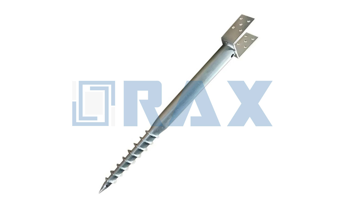
متطلبات عزم الدوران وإجراءات التركيب
إجراءات الكبس الهيدروليكي
التحقق ما بعد التركيب
📋 خطوات عملية
- Step 1: Inspect the crimp indent to ensure it is centered and symmetrical across the connector barrel.
- Step 2: Verify that no conductor strands are cut or protruding from the edges of the connector.
- Step 3: Perform a visual check of the ‘go/no-go’ gauge if the tool head includes a built-in indicator.
- Step 4: Confirm the shear head (if equipped) has properly popped off, signaling full compression.

معايير الجلفنة ومقاومة التآكل
Effective corrosion protection requires metallurgical bonding rather than simple surface coating; ISO 1461 compliance ensures long-term grid integrity in harsh environments.
In utility infrastructure, galvanic corrosion is the silent threat to structural longevity. While manufacturers rely on multiple protective coatings, only hot-dip galvanizing achieves a metallurgical bond with the base steel. This process transforms the surface into a zinc-iron alloy layer, providing a sacrificial barrier that actively resists atmospheric degradation and salt spray exposure. For grid operators, this is not just about aesthetics—it is about maintaining mechanical strength across extreme climates.
الترابط المعدني مقابل الالتصاق الميكانيكي
Many low-cost alternatives use mechanical adhesion—such as electroplating or cold galvanizing—which leaves the zinc sitting loosely on top of the substrate. Under heavy vibration or abrasive handling during transport, these layers crack and peel. Conversely, when steel is submerged in molten zinc, a series of iron-zinc alloy layers grow directly out of the steel itself. Once cooled, the coating becomes as hard as the base metal, eliminating stress concentrations and preventing debris buildup.
مراقبة الجودة والمتانة في الظروف الواقعية
Achieving a continuous, pore-free alloy layer requires rigorous environmental control throughout the pickling and galvanizing cycles. Our engineering team verifies that the process strictly adheres to ISO 1461 standards. To guarantee uniform coverage, a dedicated QC team performs a double-review protocol—inspecting 100% of products twice prior to packaging. This eliminates the risk of field failures caused by microscopic thin spots or trapped flux.
| معلمة | المواصفات | Technical Advantage | Verification Method | Service Impact |
|---|---|---|---|---|
| Galvanizing Process | ISO 1461 & ASTM A153 Class C | Consistent metallurgical bonding for maximum durability | SGS third-party certification | Ensures long-term structural integrity |
| Coating Thickness | Mean thickness exceeding 85 microns | Superior barrier protection against moisture and chemicals | Precision gauge testing | Extends lifespan in high-humidity and coastal zones |
| تشطيب السطح | Smooth, bright metallic coating | Eliminates stress concentrations and prevents debris buildup | Dual-stage visual inspection | Reduces maintenance frequency and installation friction |
| مقاومة التآكل | High-grade zinc-iron alloy layer formation | Resists atmospheric degradation and salt spray exposure | Accelerated weathering simulation | Maintains mechanical strength across extreme climates |
| Quality Control Protocol | 100% double-review by dedicated ten-person QC team | Guarantees uniform coverage and zero-defect hardware | In-house load and gauge testing per IEC 120 | Mitigates field failure risks and ensures grid reliability |
بروتوكولات الصيانة والتحقق من الأحمال
Prevent catastrophic grid failures by implementing strict load verification cycles and corrosion-resistant maintenance protocols aligned with international utility standards.
الصيانة الروتينية للطلاء والحماية من التآكل
Overhead infrastructure operates under relentless environmental stress. The primary failure mode in pole line hardware is not sudden fracture, but gradual degradation of protective barriers. When hot-dip galvanizing coatings compromise below industry thresholds, oxidation accelerates contact resistance. Utilities must schedule biannual visual and thickness inspections. A compliant standard requires a mean coating thickness exceeding 85 microns per ISO 1461. Any localized thinning or bright zinc bloom indicates early-stage depletion requiring immediate re-galvanization or sacrificial anode installation.
التحقق الميداني من الأحمال وفحص بالمقاييس
Static load capacity does not guarantee long-term performance under dynamic wind and thermal cycling. Verification protocols must shift from theoretical datasheets to empirical field validation. We mandate rigorous gauge testing conducted strictly according to IEC 120 before commissioning any tension assembly. This involves applying incremental mechanical stress to guy clamps, dead-end grips, and suspension hardware while monitoring elongation rates. If a component exhibits permanent deformation beyond 0.1% strain, it must be immediately replaced rather than recalibrated.
📋 خطوات عملية
- Step 1: Conduct initial tension calibration using calibrated hydraulic wrenches or calibrated turnbuckles to eliminate assembly slack.
- Step 2: Execute full-load proof testing at 110% of rated working load limit to verify yield point stability.
- Step 3: Perform post-test dimensional audits to confirm components remain within strict 1mm tolerance bands across all fastener axes.
- Step 4: Document load-displacement curves in digital asset registers for future predictive maintenance baselines.
مقاومة التعب والتحقق من المواد
Traditional casting methods leave internal micro-voids that act as stress concentrators during high-frequency vibration events. Hot-forged components eliminate these voids, directly increasing dynamic wind load resistance by 30%. Maintenance teams should request metallurgical certificates verifying grain flow alignment rather than relying on visual surface finishes. When auditing suppliers, prioritize hardware manufactured through closed-die forging to ensure consistent tensile strength across critical load paths.
تدقيق الامتثال والتحقق من طرف ثالث
Reliable maintenance programs require unbroken chain-of-custody documentation. Procurement teams must demand thorough SGS verification reports alongside batch-specific mill certificates. These documents should explicitly detail chemical composition, mechanical property thresholds, and coating adherence test results. Without third-party validation, internal quality control lacks the legal and technical weight required for utility compliance audits, particularly in regions with stringent regulatory frameworks like South America or Southeast Asia.
الهندسة المخصصة للتضاريس الفريدة
Rax Power transforms complex site challenges into engineered solutions through 21 years of specialized OEM execution.
سير عمل OEM لظروف التربة غير القياسية
Generic utility anchors frequently fail in unique geological profiles because they rely on standardized pull-out calculations that do not account for localized soil shear strength. Rax Power addresses this gap by implementing a rigorous OEM workflow designed specifically for non-standard terrain.
When dealing with highly corrosive acidic soils or unstable lateral clay formations, our engineering team requires precise geotechnical reports prior to manufacturing. We utilize custom mold development to alter the base geometry of the anchor, ensuring that the hardware physically interacts with the soil strata exactly as the structural design dictates.
Instead of applying a blanket coating, we engineer specific galvanizing profiles for these harsh environments. Our hot-dip galvanizing process adheres strictly to ISO 1461, achieving a mean coating thickness exceeding 85 microns to guarantee long-term durability against chemical degradation.
بروتوكولات النمذجة الأولية والاختبار لتصاميم الأبراج الحصرية
Modern utility networks increasingly utilize proprietary tower designs that demand non-standard anchoring mechanisms. For these complex structures, off-the-shelf hardware is insufficient. Rax Power leverages its 21 years of export experience to bridge the gap between theoretical engineering drawings and physical reality.
Our prototyping phase integrates advanced automation to ensure dimensional accuracy within a strict 1mm tolerance. This level of precision is non-negotiable for proprietary heavy-load towers, where even minor deviations can compromise the entire structural integrity.
Before mass production begins, we subject prototypes to exhaustive validation. Our dedicated ten-person QC team performs a double-review process, meaning 100% of prototypes are inspected twice before moving forward. This protocol eliminates potential manufacturing defects early in the lifecycle.
All load-bearing prototypes undergo rigorous in-house testing per IEC 120 standards. This ensures that the anchor can withstand the specific tension requirements of the client’s proprietary tower design without deformation or failure.
تعديل خطوة اللولب وطول الجذع للأحمال القصوى
Extreme environmental loads—such as those required for high-voltage transmission lines in severe climates—demand highly customized helical anchor geometries. Generic screw anchors cannot effectively distribute extreme torque or tensile stress in deep, high-friction soil layers.
At Rax Power, we provide specialized modifications to helix pitch and shaft length tailored to the exact load vectors of the project. Whether the requirement involves deep-buried soil stabilization or shallow rock anchoring, our engineering team adjusts the shaft diameter and helix configuration to maximize soil engagement.
These customizations are particularly vital for extreme regions like Russia, where we have deep expertise in meeting high-breaking load requirements. By altering the pitch-to-length ratio, we ensure that the anchor achieves optimal holding power without requiring excessive installation torque that could damage the driving tools.
الخلاصة
Matching helix pitch to specific soil classifications remains the primary factor in optimizing anchor performance. Standard designs fail quickly when installers ignore lateral load requirements or skip torque verification protocols. We hold every manufactured rod to a strict one-millimeter tolerance. Twenty-one years of export experience proved dimensional accuracy prevents premature tower settlement under heavy wind loads.
- Avoid skipping galvanizing checks; coating thickness below eighty-five microns invites rapid corrosion in humid environments.
- Never pair drive adapters with mismatched shaft diameters; improper torque strips installation threads and compromises structural integrity.
- Consult our engineering notes for early design validation. Our technical staff handles preliminary torque calculations with zero commercial obligation during your planning phase.
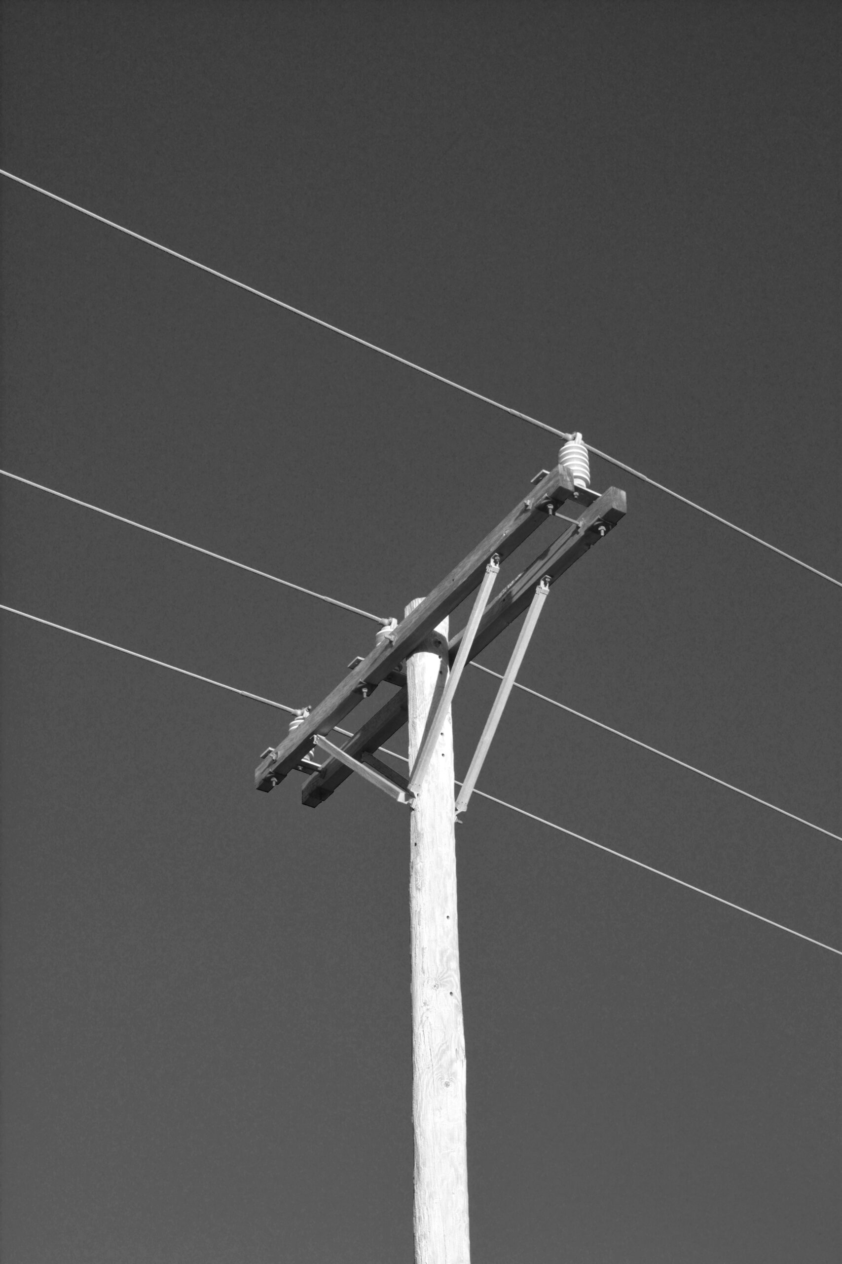
عازل مثبت على العمود يمسك بالمواسير الرأسية على مسافة ثابتة من سطح العمود، مما يحمي الكابلات ويحافظ على الفصل عن الموصلات والمعدات الأخرى.
كيف تقاوم المراسي اللفلية قوى الرفع؟
تقاوم هذه المراس قوة الرفع من خلال التشابك الميكانيكي للصفائح اللولبية مع طبقات التربة المضغوطة. ومع زيادة عزم الدوران أثناء التركيب، تنضغط التربة المحيطة بإحكام حول العمود والشفافات. يخلق هذا الانخراط الاحتكاكي أساساً مستقراً يعمل على مقاومة أحمال الشد الرأسية بفعالية. يضمن العمق المناسب للتركيب تفاعل المرساة مع الطبقات المتينة بدلاً من التربة السطحية المفككة.
ما هي أفضل المواد لألواح الحلزون؟
تظل درجات الصلب منخفضة الكربون والسبائك عالية القوة المعيار الصناعي المعتمد لتصنيع ألواح اللولب. توفر هذه المواد قابلية ممتازة لللحام وقوة شد وتوافقًا مع أنظمة الطلاء الواقي. تمتد فترة الخدمة بشكل كبير في البيئات المسببة للتآكل مثل المناطق الساحلية عند استخدام الأنواع المجلفنة أو المطلية بالإيبوكسي. يعتمد اختيار المادة في النهاية على مواصفات المشروع والتعرض البيئي وطاقات الحمل المطلوبة.
كيف يؤثر نوع التربة على عمق التركيب؟
تتطلب التربة الطينية الكثيفة والتربة الرملية عادةً أعماق اختراق أقل نظرًا لارتفاع قدرتها التحملية الطبيعية. تتطلب التربة الردمية المفككة أو التربة السطحية العضوية تركيبًا على أعماق أكبر للوصول إلى الطبقات الفرعية المستقرة والمدمجة. يضبط المهندسون تباعد الروؤس اللولبية وطول العمود استنادًا إلى نتائج المسح الجيوتقني. يمنع التصنيف الصحيح للتربة الهبوط المبكر ويضمن الاستقرار الهيكلي طويل الأمد.
ما هي قيم عزم الدوران التي تدل على الثبات الصحيح؟
يرتبط عزم التركيب ارتباطاً مباشراً بالقدرة التحملية القصوى ويُعد مقياساً رئيسياً لمراقبة الجودة. يراقب الفنيون الميدانيون مقاييس العزم باستمرار لضمان وصول المرساة إلى عمق التحمل المصمم. قد يشير العزم الزائد إلى الاصطدام بالصخر الأساسي أو الحصى المتماسك، ما يستدعي تعديل العمق. تؤكد قراءات العزم المتسقة عبر تركيبات متعددة تجانس ظروف التربة ودقة معايرة المعدات.
أي الصناعات تستخدم المراسي الأرضية هذه؟
Utility companies widely deploy screw anchors for transmission towers, substations, and fiber optic support structures. Solar farm developers utilize them to secure mounting frames across diverse terrain conditions. Telecommunications firms rely on these systems for stable antenna mast foundations in remote areas. Construction projects also incorporate them for retaining walls and temporary structural bracing.