
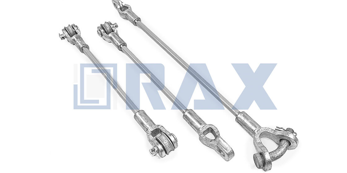
تصفحات مواصفات المعدات تدرج تصنيفات مقاومة الشد وتتوقف عند ذلك. النص الدقيق يخبر بقصة مختلفة — ثبّت مراساً بزاوية تزيد عن 5 درجات عن محاذاة حمل سلك السند، وستتدهور سعة الحمل المصنفة بسرعة. معامل واحد. خمس درجات. الفرق بين عمود يقف لعقود وعمود يميل نحو الطريق السريع بعد شتاء ممطر واحد. لا يزال فرق الميدان يعامل اختيار المراس كأنه أمر عابر. إنه ليس كذلك. دليل اختيار مراس التربة القائم على ظروف التربة الفعلية هو ما يفصل بين تركيب يدوم 30 عاماً ومطالبة بضمان.
يرسم هذا المقال خريطة عائلات المراس الرئيسية إلى الجيولوجيا التي تنتمي إليها — تصاميم ألواح الدفن للترب المشبعة اللينة، والأنظمة ذات القضيب الدافعي للترب الطينية الكثيفة، والمراس المحقون حيث يقرأ سجل الحفر جيولوجيا مختلطة. نغطي المفاضلات التي تفصل المشاريع في يوم التركيب: لماذا تلتف المراس الحلزونية بقوة في الترب الصلبة، وكيف تتصرف الألواح المتوسعة بشكل مختلف في الطين مقابل الصخور المكسورة، وما الذي تخبرك به اختبارات الحمل الميدانية فعلياً والذي لا تخبرك به بطاقات البيانات أبداً. بعد 23 عاماً من اختبارات الحمل الداخلية وفق معايير IEC 120 في شركة Rax Power، تتكرر أنماط الفشل عبر كل قارة نصدّر إليها. الهدف هنا هو جعلها قابلة للتنبؤ وقابلة للوقاية.

ترجمة بيانات الجيوتقنية لمراسي التربة
تقارير الجيوتقنية هي المؤشر الأدق وحيداً لسعة تحمل مراس التربة. سوء تفسير قيم SPT N أو تجاهل تقلبات منسوب المياه الموسمي يؤدي مباشرة إلى فشل الأساس.
استخدام قيم SPT N لتحديد قدرة تحمل التربة
قيمة SPT N (الاختبار القياسي للاختراق) — عدد الضربات المطلوبة لدفع عيّنة 12 بوصة في التربة — هي المقياس الحرج لتحديد اختيار المرسى. ترتبط مباشرة بكثافة التربة ومقاومتها القص، وهي العوامل الحاكمة في مقاومة سحب المرسى. قيم N المنخفضة (0–10) تشير عادةً إلى رمال رخوة أو طين لين حيث قد تحقق المراس ذات القضبان التقليدية قبضة غير كافية. في هذه الظروف، تكون المراس ذات المساحات السطحية الكبيرة مثل المراس الحلزونية المتعددة أو ألواح التقاطع المتوسعة مطلوبة لتوزيع الحمل على حجم ترب أكبر.
في المقابل، تمثل قيم N العالية (30–50+) حجراً كثيفاً أو ترباً صلبة حيث تصبح قوة التركيب العامل المحدد. محاولة دفع مراس لوحة قياسية إلى هذه الأساسات يؤدي غالباً إلى توقف المعدات أو فشل قضيب المرسى هيكلياً أثناء التركيب. للطبقات عالية الكثافة، المراس المتوسعة أو المراس الحلزونية ذات العمود المربع ثقيل الحمل ضرورية لاختراق الأرض والوصول لسعة عزم الدوران المطلوبة.
نعدل أقطار قضباننا وتكوينات الحلقات بشكل متكرر بناءً على ملفات قيم N هذه. في خبرتنا بتوريد المشاريع إلى روسيا وجنوب شرق آسيا، استخدام مواصفات الكتالوج القياسية لظروف ترب متغيرة هو وصفة للفشل. بدلاً من ذلك، نطبق تقنيات الحدادة الساخنة لإنتاج أعمدة بالقوة الشدية المحددة اللازمة لتحمل عزوم التركيب العالية في الترب الكثيفة دون المساس بالسلامة الهيكلية للمرسى.
التخفيف من تأثيرات تغير التربة الموسمي على سعة التحمل
الترب وسط ديناميكي يفقد قوته مع زيادة محتوى الرطوبة. تقرير جيوتقني يُؤخذ خلال الموسم الجاف غالباً ما يعطي قيم SPT وزوايا الاحتكاك أعلى بكثير مما هو موجود خلال الموسم الممطر. في الترب الحبيبية، يقلل ارتفاع منسوب المياه الجوفية الإجهاد الفعال، مما يقلل بدوره مقاومة الاحتكاك على سطح فشل المرسى. في الترب المتماسكة، يمكن أن يقلل التشبع المقاومة القصية بنسبة 50% أو أكثر، محوّلاً مراساً مستقراً إلى عبء.
للتخفيف من هذه المخاطر الموسمية، يجب على المهندسين تطبيق عامل أمان تحفظي على سعة التحمل المحسوبة، يتراوح عادةً من 1.5 إلى 2.0، حسب تباين الترب. من الضروري أيضاً التحقق من أن عمق المرسى يمتد أسفل منطقة تقلبات منسوب المياه الموسمي. لشركائنا في التصدير الذين يتعاملون مع تقلبات موسمية متطرفة، نضمن أن مجلفنتنا بالغمر الساخن — التي تتجاوز 85 ميكرون وفق معيار ISO 1461 — تحمي المرسى من التآكل المتسارع الناتج عن بيئات الترب الرطبة، حفاظاً على قوة التصميم طوال عمر النظام.
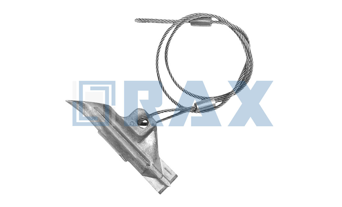
متطلبات حمل أعمدة المرافق الكهربائية لمراسي التربة
فشل المراس نادراً ما ينبع من ضعف مقاومة الشد الرأسية؛ يحدث لأن المهندسين يحسبون بشكل خاطئ قوى المتجهات الأفقية ويتجاهلون حدود التوتر الديناميكي لنظام سلك السند.
حساب توزيع الحمل الأفقي وتوتر أسلاك السند
أعمدة المرافق تعمل كأرجل متصالبة رأسية، لكن مراسي التربة يجب أن تدير القوى الناتجة عن قص الرياح وأحمال الموصلات غير المتوازنة. التحدي الهندسي الحرج هو تحليل هذه المتجهات الأفقية إلى الشد المحوري المطبق على سلك السند. النسبة بين طول المقدمة وارتفاع العمود تملي هذه الزاوية، ننقل العبء الهيكلي بين قوة ضغط العمود وسعة تحمل الشد للمرسى. زاوية مقدمة ضحلة تضخم الحمل الضاغط على عمود المرافق، بينما زاوية أشد تزيد بشكل كبير قوة السحب الرأسية على المرسى.
في خبرتنا بمراجعة تركيبات الشبكات الدولية، السبب الجذري لزحف المراس المبكر هو دائماً التشديد الأولي غير الملائم. تفتراضي المعايير الصناعية تشديداً أولياً بين 8% إلى 15% من قوة الكسر المُصنفة (RBS) لسلك السند لتحميل مسبق للنظام وامتصاص أحمال الصدمة الديناميكية. التشديد الزائد يتجاوز فوراً سعة تحمل الترب الموضعية، مما يؤدي إلى سحب المرسى تدريجياً. في المقابل، يقلل التشديد الناقص من انحراف العمود المفرط أثناء أحداث الرياح القصوى. نحن نعاير بشكل محدد مشابك السند ذات الحدادة الساخنة وقضبان المراس للحفاظ على نافذة التوتر الدقيقة 8-15%، مضمّنين أن العتاد يتوافق انسجاماً مع السلك تحت الإجهاد الأقصى.
الموازنة بين ملفاتي التحميل المركب وعوامل الأمان
أحمال المراس الواقعية نادراً ما تكون رأسية أو أفقية بحتة. يجب على المهندسين حساب ملف تحميل مركب يلخّص الوزن الميت للهيكل، وحمل الجليد، وسحب الرياح، وتوتر الخط. هذا يتطلب تحليل المجموع المتجهي لهذه القوى لتحديد الحمل النهائي الحقيقي الذي يجب أن يقاومه المرسى. إذا كانت ورقة مواصفات المرسى توفر فقط سعة التحمل الرأسية الأساسية دون اعتبار لأحمال القص والشد المركبة، فإنها تخلق عمى تصميم هائل للمشروع.
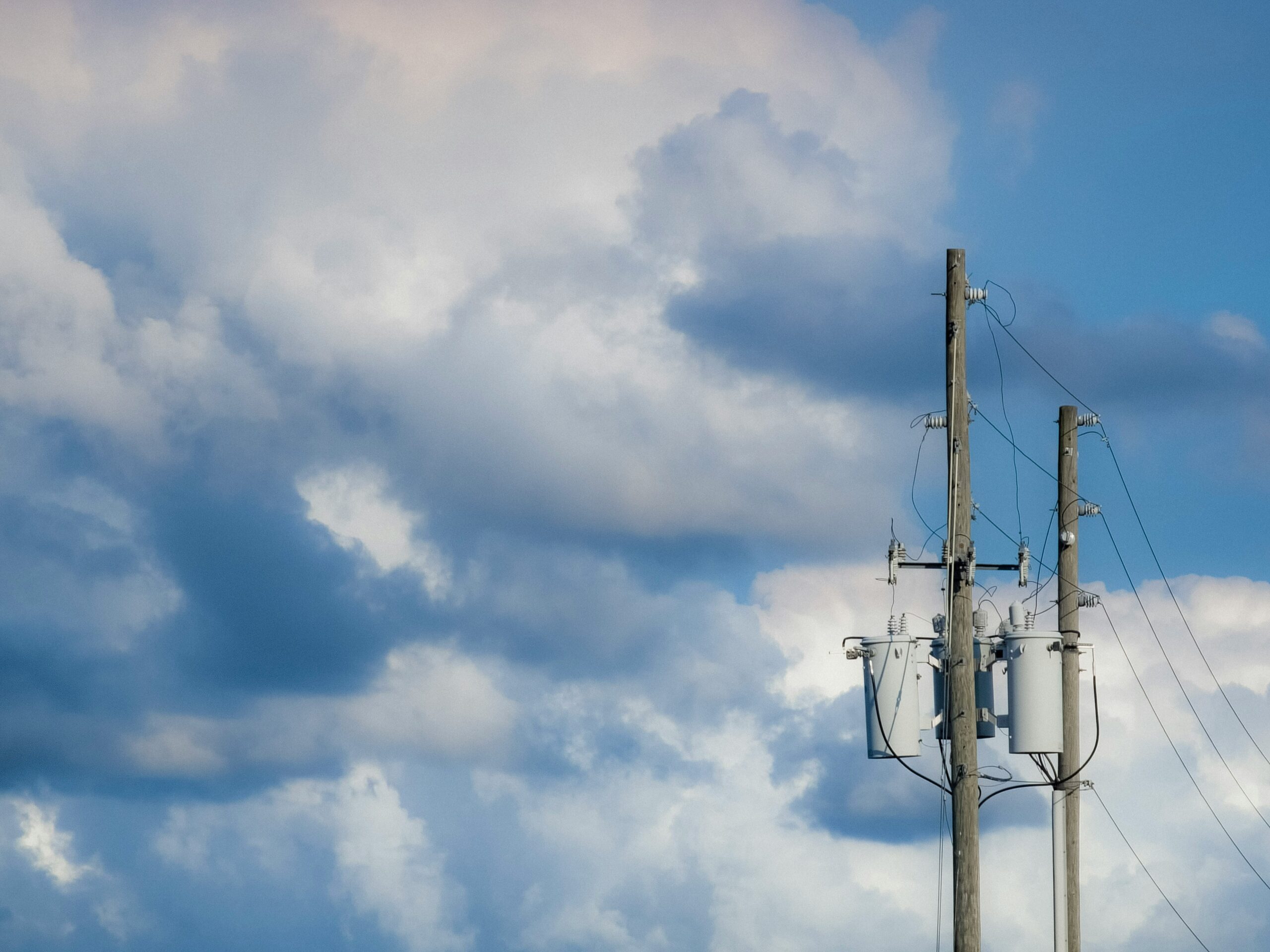
مراسي ألواح الدفن للترب اللينة
In loose soil mechanics, the anchor’s primary defense against pull-out is surface area, not depth. Without a broad plate, the anchor creates a localized shear plane that fails instantly under tension.
ميكانيكا مقاومة السطح
Soft soils such as marsh, loose sand, or clay possess low shear strength. When a guy wire is tensioned, a standard narrow shaft anchor simply slices through the ground. Bearing plate anchors combat this by maximizing the surface area perpendicular to the load. This geometry distributes the tensile force over a larger volume of soil, effectively engaging more mass to resist the pull and preventing the classic ‘drag-out’ failure seen in unstable terrain.
السلامة الهيكلية عبر الحدادة الساخنة
Soft soils are dynamic; they settle and shift unpredictably. If the bearing plate is manufactured using traditional casting, microscopic voids can create weak points that fracture under shifting loads. We utilize hot-forging technology for our bearing plates. This process compresses the steel grain structure, eliminating internal voids and providing superior tensile strength and impact resistance compared to cast alternatives. The result is a plate that withstands the initial shock of installation and the long-term stress of soil movement without cracking.
الدفاع التآكلي في الترب المشبعة
Soft soil environments typically retain high levels of moisture, creating a highly corrosive underground setting. Standard surface treatments often degrade rapidly in these conditions. Our manufacturing protocol adheres to ISO 1461 hot-dip galvanizing standards, ensuring a mean coating thickness that surpasses 85 microns. This dense zinc barrier is critical for long-term reliability, as it provides the necessary cathodic protection to prevent rust from compromising the structural integrity of the anchor plate over decades of service.
| Technical Feature | المواصفات | Application Advantage | معيار الجودة |
|---|---|---|---|
| Load Distribution Mechanism | Large Surface Bearing Plate | Optimized to maximize soil resistance in soft/loose terrains, preventing pole tilting and pull-out. | In-house load testing conducted per IEC 120 standards. |
| Structural Integrity | Hot-Forged Steel Construction | Provides superior tensile strength and impact resistance compared to traditional casting methods. | SGS verified materials and processes. |
| مقاومة التآكل | ISO 1461 Hot-Dip Galvanizing | Mean coating thickness exceeds 85 microns, ensuring durability in saturated underground environments. | 10-person QC team monitors coating thickness at every stage. |
| Precision & Reliability | OEM/ODM Custom Molds | Tailored plate dimensions and rotation angles for specific soft soil engineering requirements. | 100% Double-review process inspected twice before packaging. |
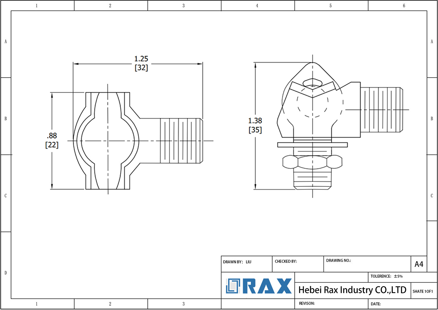
مراسي القضبان الدافعية للترب الطينية الكثيفة
Rod-driven expanding anchors are the default choice for dense clay installations because they displace rather than remove soil, maintaining the very cohesion that gives clay its holding power. The failure mode isn’t usually the anchor body—it’s drive rod buckling and incomplete expansion in high-plasticity soils.
In dense clay environments (SPT N-values of 20 to 50), utility contractors face a fundamental selection problem: helical anchors fight the soil’s shear resistance during rotation, while grouted systems add unnecessary installation time. Rod-driven expanding anchors solve this by using a solid drive steel to punch a pilot hole, then pulling the anchor head back through the formation to lock the helix or expanding plate into undisturbed clay. The result is high bearing capacity without the torque requirements of screw anchors or the cure time of cement-based systems.
لماذا تتطلب الترب الطينية الكثيفة هندسة مراس مختلفة
Dense clay creates two conflicting engineering challenges. First, it offers excellent ultimate holding capacity due to high undrained shear strength—often exceeding 100 kPa in heavily overconsolidated deposits. Second, it resists penetration. A standard cross-plate anchor that performs adequately in sandy loam will refuse to reach target depth in clay with a plasticity index above 30, or it will arrive distorted and structurally compromised.
The rod-driven expanding anchor addresses this through a two-stage deployment. The drive rod carries the unexpanded anchor to depth as a compact assembly. Once at the target strata, upward tension pulls the cam or expanding mechanism open, forcing the bearing plate against the undisturbed clay face. Because the clay was never fully excavated, it retains its natural interparticle bond and delivers holding capacity within hours of installation—no settling period required.
فشل قضيب الدفع: التكلفة الخفية للصلب الرديء
Achieving the necessary balance of impact resistance and ductility in dense clay requires hot-forged drive rods manufactured from medium carbon steel like AISI 1035. Heat-treated to a Brinell hardness of 200-250 HB, they withstand the repeated percussive loading that dense clay demands—conditions under which cast drive rods, while cheaper, fail catastrophically. Our internal testing across 23 years of field experience consistently shows forged rods maintaining dimensional integrity after 50+ installation cycles, whereas cast variants exhibit visible bending after as few as 5 cycles in clay with penetration resistance above 300 kPa.
الحماية من التآكل: أمر لا يقبل المساومة لتركيبات الطين
Dense clay creates a low-oxygen, high-moisture environment that accelerates localized pitting corrosion on bare steel. The defense is hot-dip galvanizing applied after fabrication—not electroplating or mechanical zinc coating. Under ISO 1461, anchor assemblies in corrosive soil environments require a mean coating thickness exceeding 85 microns. This threshold is not arbitrary; it provides the sacrificial zinc mass needed for a projected 50-year service life in soil resistivity conditions common to saturated clays (typically 2,000 to 5,000 ohm-cm).
بروتوكول التحقق الميداني من الحمل لمراسي الترب الطينية
Dense clay exhibits time-dependent strength gain due to thixotropic recovery after installation disturbance. An anchor load-tested at 2 hours post-installation may show only 65% of the capacity it achieves at 72 hours. Tender specifications for utility infrastructure projects increasingly require proof testing at both intervals. The standard procedure involves applying 50% of design load initially, holding for 10 minutes, then ramping to 100% design load while monitoring creep displacement. Acceptance criteria typically limit displacement to less than 25mm over a 60-minute observation window at sustained proof load.
📋 خطوات عملية
- Step 1: Pre-installation: Confirm clay SPT N-value is between 20-50 and verify no cobbles or boulder layers in the drive path using hand auger probing.
- Step 2: Drive the anchor to specified depth using a percussion rod system; monitor rod straightness every 0.5m of advancement—if rod deviation exceeds 3 degrees, abandon and relocate.
- Step 3: Expand the anchor by applying controlled upward tension; the expansion force should reach 1.5x the anchor’s rated working load to ensure full bearing plate deployment.
- Step 4: Wait a minimum of 24 hours before proof testing to allow clay pore pressure equalization and initial thixotropic recovery.
- Step 5: Execute load test per IEC 120 methodologies: document load-displacement curve, confirm linear elastic behavior in the initial loading phase, and verify no progressive creep at design load.
متى تكون مراسي القضبان الدافعية خياراً خاطئاً في الطين
Despite their advantages, rod-driven expanding anchors have documented limitations in specific dense clay conditions. In highly expansive clays with a swelling potential exceeding 6%, cyclic wetting and drying can progressively reduce the effective bond between the bearing plate and the soil matrix. Projects in these conditions—common in regions with pronounced dry and wet seasons—should consider helical anchors with larger diameter shafts, or grouted tieback systems for critical load applications. The rod-driven expanding anchor remains the optimal solution for stable, saturated dense clays where installation speed and immediate load capacity outweigh long-term cyclic loading concerns.
For B2B procurement teams evaluating rod-driven anchor suppliers, the differentiating factors are not the catalog drawings—those look identical across manufacturers. The real selection criteria are drive rod metallurgy documentation, ISO 1461 galvanizing certificates with thickness test results, and the supplier’s willingness to provide IEC 120 load test data from production lot sampling. We provide this documentation as standard practice because these are the exact verification steps that rejection-prone suppliers skip.
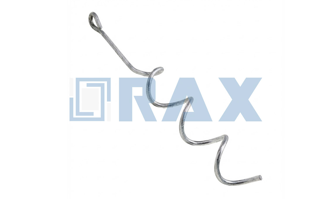
مراسي الترب الحلزونية للترب الصلبة
In dense or rocky soils, the critical engineering failure mode for earth anchors shifts from vertical pull-out to structural yielding during installation; the hardware must survive extreme torsional stress before it can ever engage the soil’s holding capacity.
When deploying guy wire supports in hard ground environments—such as compacted caliche, glacial till, or dense clay—contractors consistently face the issue of torque refusal. As the anchor meets dense resistance, the required installation torque spikes dramatically. This is where standard cast anchors frequently fail, snapping at the flight or permanently twisting the drive rod. We frequently address this exact pain point for our utility partners in extreme-climate markets like Russia, where dense, frozen soil profiles demand hardware that can absorb massive torsional impact without fracturing.
تحسين الاختراق في الطبقات عالية الكثافة
Spiral flight earth anchors are engineered specifically to mitigate these high-torque installation shocks. The continuous helical geometry allows for a smoother, more consistent rate of penetration, channeling the mechanical force downward rather than allowing it to concentrate and fracture the anchor head. Because our manufacturing process utilizes high-temperature forging rather than traditional casting, the molecular grain structure of the steel flows continuously along the shaft. This structural uniformity eliminates the micro-porosities that lead to sudden shear failures when a powered installer hits a subterranean rock shelf or hardpan layer.
While expanding anchors are often cited as an alternative for hard rock conditions, they require precise pre-drilling and extensive manual excavation. In remote utility deployments where minimizing equipment footprint and labor costs is critical, spiral flight anchors bypass this bottleneck by displacing dense soil laterally as they advance. However, field operators must remain vigilant, as the structural advantage of a forged shaft only holds if the installation torque does not exceed the drive head’s engineered yield limit.
| المعاملات الفنية | المواصفات | Engineering Advantage |
|---|---|---|
| Core Manufacturing | Hot-Forged Steel Technology | Superior structural integrity prevents drive-rod bending during high-torque installation in dense or hard soil. |
| Corrosion Defense | >85 Microns Hot-Dip Galvanizing (ISO 1461) | Thick, uniform coating provides long-term protection against underground corrosion and soil acidity. |
| Flight Configuration | Helical Round or Square Shaft | Optimized pitch design maximizes torque transfer and penetration efficiency in compacted earth. |
| Load Verification | IEC 120 In-House Load Testing | Certified pull-out capacity ensures reliable holding power for high-tension guy wire applications. |
| Quality Control | 100% Double-Review Inspection | Zero-defect assurance guarantees dimensional accuracy for immediate field deployment. |

مراسي الترب المحقونة للجيولوجيا المختلطة
Mixed geologies force the integration of grouted and mechanical earth anchors, creating complex load-transfer dynamics. Maintaining a unified safety factor demands strict metallurgical consistency and standardized interface hardware.
حل تكامل أنظمة مراسي المختلطة
Utility projects rarely enjoy uniform soil profiles. When a transmission line crosses from dense clay into rocky terrain, site engineers must transition from driven expanding anchors to grouted earth anchors. The primary pain point in these hybrid arrangements is not just the installation method, but the hardware interface. Disparate thread patterns, undefined load axes, and unverified safety factors frequently compromise the structural integrity of the pole line.
To eliminate integration complexity, engineers must standardize the anchor-to-guy wire interface, regardless of the below-ground mechanism. We address this by applying strict hot-forging techniques to our expanding and cross-plate anchor heads. This ensures the connecting tie rods maintain consistent yield strengths across the entire project. Field crews can swap anchor types based on geotechnical data without redesigning the above-ground guy wire assembly or worrying about mismatched hardware.
التحقق من الحمل في الترتيبات الهجينة
This reality demands aggressive in-house verification. We subject all anchor assemblies—whether destined for soft soil or solid rock—to strict load and gauge testing per IEC 120 standards. Our dedicated 10-person QC team executes a 100% double-review process before packaging, ensuring that every grouted anchor rod and mechanical expanding anchor meets identical failure thresholds.
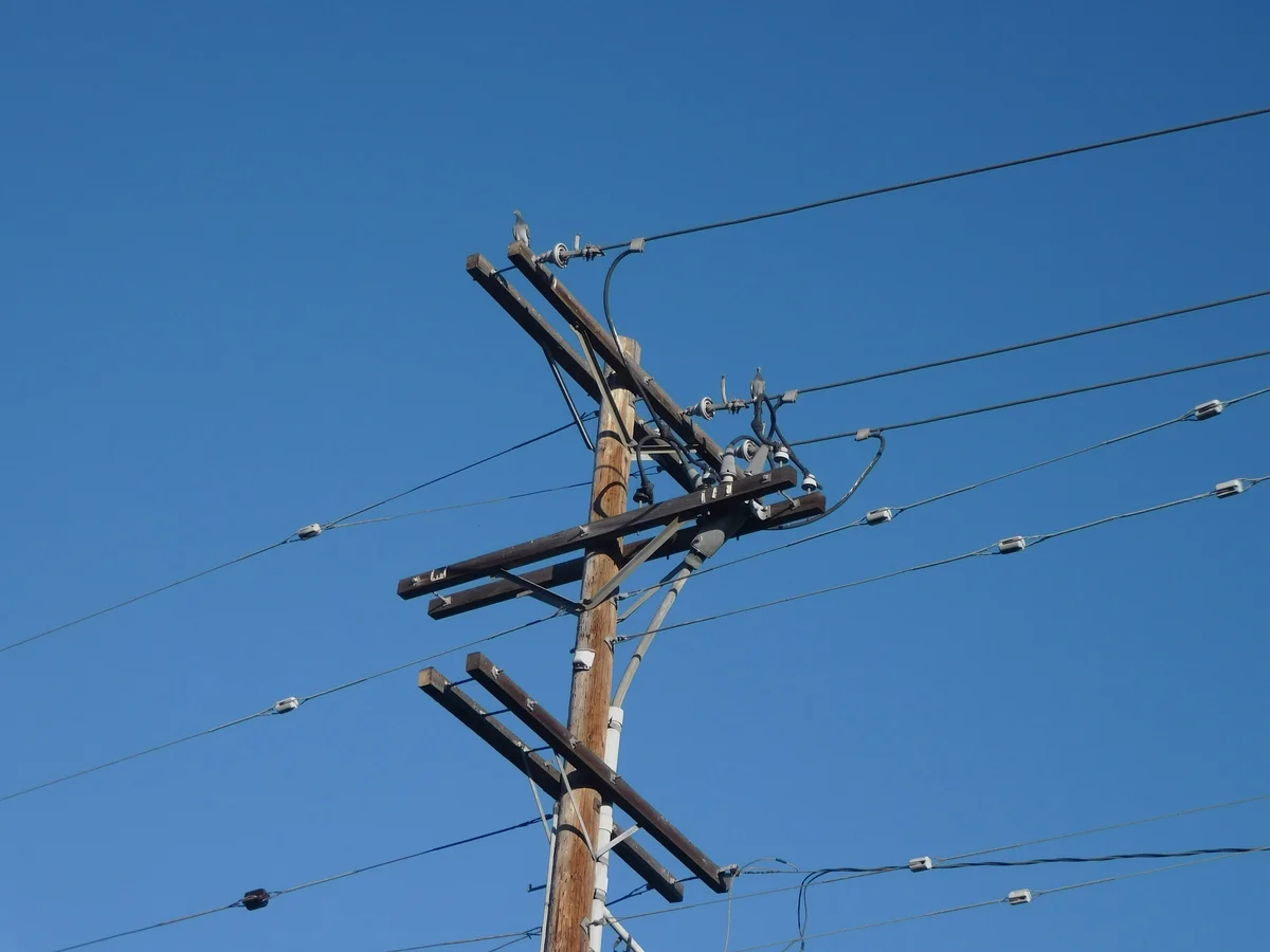
إرشادات تركيب مراسي التربة والفروقات
Earth anchor holding capacity failures are rarely manufacturing defects; they are almost exclusively the result of field parameter oversights. Precise installation angles and depth verification dictate whether an anchor holds or pulls out.
معالجة زوايا التركيب الحرجة ومتطلبات العمق
An earth anchor must be installed so that the anchor rod aligns perfectly with the resultant guy wire load. If the anchor is driven at an angle offset from the guy wire’s direct line of pull, the tension creates a severe lateral bending moment on the rod. This misalignment induces cyclic fatigue and gradually wallows out the soil around the shaft, ultimately leading to premature anchor pull-out or rod yielding. Field technicians must ensure the drive angle points directly at the intended pole attachment point.
Depth is equally critical. The anchor’s bearing surface—whether a helical plate, cross-plate, or expanding bail—must be seated completely below the active frost penetration line and topsoil layer into undisturbed, load-bearing soil. Shallow installations in loose topsoil will fail immediately under high wind loads, as the soil simply does not possess the required shear strength to resist the uplift.
In our engineering facility, we utilize hot-forging technology to ensure the tensile integrity of our expanding anchors and helical shafts, and our lab verifies load capacities per IEC 120 standards. However, our internal field data consistently shows that even an 85-micron hot-dip galvanized, high-tensile anchor will underperform if the installation vector is misaligned by just a few degrees. The hardware is only as strong as the geometry of its installation.
التغلب على إغفالات المعاملات في ظروف ترب صعبة
The most expensive oversight in utility construction is assuming uniform soil composition across an entire right-of-way. In challenging geologies—such as mixed clay, saturated silts, or dense gravel—contractors frequently misjudge the torque-to-capacity ratio. While helical anchors offer rapid installation, blindly driving them without reading the torque feedback means installing blind. Torque correlation factors vary wildly between stiff clays and loose sands, meaning standard capacity charts are useless without site-specific calibration.
Overcoming these site variables requires a total cost of ownership (TCO) approach to anchor selection. Helical anchors demand high equipment costs (hydraulic drive motors) but minimize labor and eliminate concrete cure times. Conversely, cross-plate and expanding anchors require manual augering and heavy backfilling labor but provide superior bearing area in highly expansive or saturated soils where helical flights might simply churn the ground.
📋 خطوات عملية
- Step 1: Align the drive rod on a direct vector matching the guy wire attachment point on the utility pole.
- Step 2: Monitor installation torque continuously and correlate the readings with site-specific soil shear strength data.
- Step 3: Ensure the anchor bearing element is driven below the active topsoil and frost lines into competent strata.
- Step 4: Apply a pre-tension load to mechanically seat the anchor against the soil face before final clamp tightening.
التحقق من الحمل وصيانة مراسي التربة
Datasheet load ratings are theoretical baselines; true structural integrity depends entirely on rigorous field torque-to-load verification and proactive galvanic corrosion evaluation.
تطبيق ارتباط سعة عزم الدوران واختبار الحمل الميداني
Engineers frequently face a dangerous gap between laboratory-rated holding capacities and actual performance in unpredictable geology. Torque capacity correlation provides a critical mathematical bridge during installation. By monitoring the final installation torque of expanding or helical anchors using a calibrated torque wrench or digger derrick, crews can apply a site-specific torque-to-hold ratio to verify that the anchor has achieved the required soil bearing capacity before the guy wire is tensioned.
Establishing a reliable baseline for these field calculations requires uncompromising manufacturing controls. We execute strict in-house load testing per IEC 120 standards to determine the absolute yield and breaking limits of our hardware before it ever leaves the facility, ensuring that any field discrepancies point to geotechnical anomalies rather than material defects.
تقييم الحماية التآكلي وعمر المراسي المجلفنة
Subterranean corrosion silently degrades infrastructure integrity long before visible surface signs appear. While hot-dip galvanizing can theoretically provide decades of protection, the actual service life of an underground anchor is dictated by localized soil pH, chloride content, and stray currents. A galvanized coating that is too thin or mechanically damaged during installation in rocky terrain will suffer accelerated capacity loss, leading to premature guy wire relaxation and eventual pole failure.
Mitigating this hidden degradation requires high-grade material engineering. We refuse to compromise on metallurgical integrity, utilizing superior hot-forging rather than traditional casting to eliminate internal porosity. This dense, high-strength foundation is paired with leading hot-dip galvanizing technology compliant with ISO 1461, guaranteeing a mean coating thickness strictly exceeding 85 microns to withstand aggressive soil chemistry across global utility markets.
الخلاصة
[ {“type”: “paragraph”, “content”: “Matching the right anchor to your soil profile beats picking the cheapest option every time. Bearing plates handle soft saturated ground. Rod-driven anchors grip dense clay. Spiral flights bite into hard soil. Grouted systems bridge mixed geology. Get that match wrong, and you’ll watch poles tilt within the first freeze-thaw cycle.”}, {“type”: “paragraph”, “content”: “Corrosion kills anchors faster than overload. Our ISO 1461 galvanizing exceeds 85 microns — the difference between a 15-year and 50-year service life in aggressive soils. We run IEC 120 load tests in-house on every batch. Send us your geotechnical reports and guy wire tension specs. Our engineers will validate your anchor selection before you commit to an order — no obligation, just hard numbers.”} ]عازل مثبت على العمود يمسك بالمواسير الرأسية على مسافة ثابتة من سطح العمود، مما يحمي الكابلات ويحافظ على الفصل عن الموصلات والمعدات الأخرى.
كيف نوازن مفاضلات اختيار المراس؟
Balancing anchor selection involves evaluating soil type, required holding capacity, and installation equipment constraints. Helical anchors offer excellent load-bearing in solid soils, while expanding anchors suit rocky terrains. Engineering teams must weigh installation speed against specific load requirements to ensure optimal grid reliability. At Raxpower, we recommend conducting thorough geotechnical analyses to optimize this matrix effectively.
أي التربات تصلح للمراس الحلزونية أفضل؟
Helical earth anchors perform exceptionally well in cohesive soils like clay, dense sand, and stable loam mixtures. They are designed to screw into the earth, compacting the soil around the helical plates to generate superior holding strength. However, they are generally not recommended for rocky or heavily compacted gravel terrains without pre-drilling. Matching the helix diameter to the specific soil density is critical for achieving the required holding capacity.
متى يجب استخدام مراس الألواح المتوسعة؟
Expanding anchors are ideal when installing utilities in hardpan soils or terrains where the topsoil is too loose to hold standard anchors. Once driven to the required depth, the anchor’s cutting blades expand outward into the undisturbed soil. This expansion creates a massive resistance footprint capable of handling heavy tensile loads. They are highly effective in environments where excavation is restricted or extremely difficult.
ما فوائد مراس بلا مفك؟
No-wrench screw anchors provide exceptional installation speed and require significantly less heavy machinery compared to traditional buried anchors. They feature a specialized forged helix that allows crews to install them manually using a torsion bar or light mechanical equipment. This design is particularly advantageous for remote utility sites or emergency restorations where access is heavily restricted. They provide immediate, high-strength holding power once properly seated into the soil.
هل يؤثر المجلفنة على متانة المراس؟
Hot-dip galvanization drastically extends anchor durability by creating a metallurgical barrier against aggressive soil corrosion. High-quality galvanizing ensures the steel hardware maintains its structural integrity even in highly acidic or moisture-laden ground environments. The thickness of the zinc coating directly dictates the lifespan of the underground infrastructure. Raxpower rigorously adheres to ISO 1461 standards, guaranteeing superior anti-corrosion performance for demanding environments.