
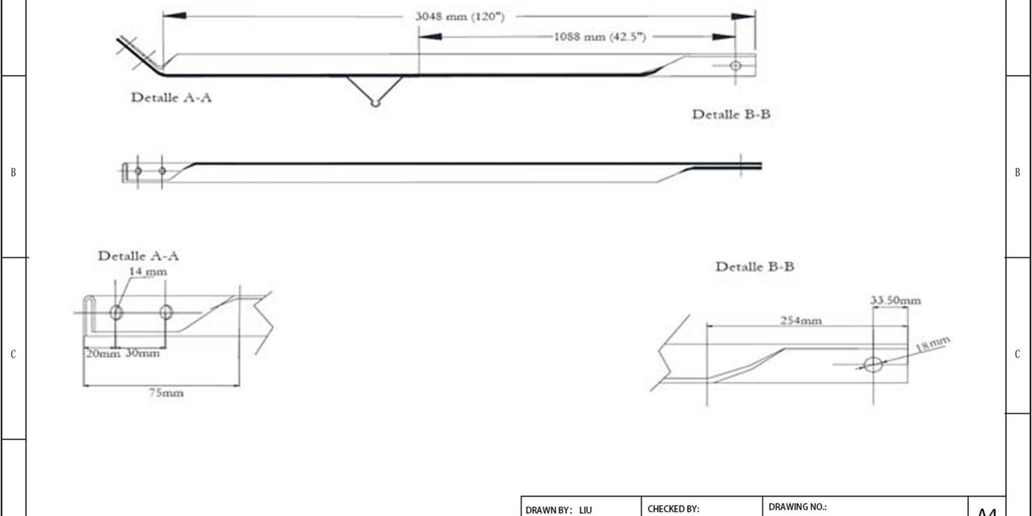
تعامل معظم فرق المشتريات مع مواصفات ذراع الممر كتمرين جدول بيانات، حيث تتحقق من تسامحات المليمتر وأوزان الزنك قبل توقيع أوامر الشراء. هذا النهج يفوّت نقطة الفشل الفعلية. نصنع أذرع عبور فولاذية في شركة Rax Power وفق تسامح أبعادي صارم يصل إلى 1 مم، لأن ثقوب المسامير غير المحاذاة تخلق إجهاد قص عند واجهة العمود. هذا الإجهاد يتسبب في تشقق اللحامات قبل أن تتعرض الخطوط لأحمال الرياح.
سترى كيف تُمكّنك هذه التسامحات من الاستعداد لظروف النشر الواقعية. ابدأ باستراتيجيات أساس الألواح الشمسية ومناطق تثبيت أعمدة الكهرباء الحضرية حيث تفرض الحقوق الضيقة هندسة المعدات. بعد ذلك، تتبع عزم التركيب يرتبط بشكل مباشر بـ تصنيفات التربة. ثم تفحص أيزو 1461 معايير الجلفنة التي تصمد أمام اختبارات رذاذ الملح الساحلي. إتقان هذه المعلمات يلغي التخمين أثناء عمليات التدقيق الأمني ويضمن تكلفة متوقعة لكل وحدة عبر محفظة شبكتك.
تطبيقات مراسي بلا مفتاح
استراتيجيات نشر أساس مصفوفات الطاقة الشمسية
مراسي البراغي بلا مفتاح تُبسّط بناء مزارع الطاقة الشمسية واسع النطاق من خلال تمكين التركيب اليدوي السريع بالدفع دون الحاجة إلى معدات هيدروليكية متخصصة. تتجاوز فرق العمل نوافذ الحفر متعددة الأيام وتثبت أنظمة الدعم مباشرة على الركائز المضغوطة أو الحبيبية. ندمج هذه الوحدات مباشرة في تصاميم الأرضيات القياسية للمرافق لاختصار ساعات العمل مع الحفاظ على السلامة الهيكلية عبر البناء بالفولاذ المطروق ساخناً. يتحقق فريق الهندسة لدينا من ميلان وترتيب المراسي مقابل القضبان القياسية للدعم لمنع عدم المحاذاة أثناء النشر واسع النطاق.
- سير عمل النشر السريع: تُمكّن مشغّلات التأثير اليدوية من نشر الفرق بشكل متزامن عبر مناطق الموقع المتدرجة، مما يقلل تكاليف التجنيد لمقاولي EPC الذين يديرون مشاريع تتجاوز 50 ميجاوات.
- توافق المعدات: تتفاعل الأذرع الآلية بدقة مع الهياكل الفرعية ومشابك السلك المسلّم المجلفنة، مما يلغي الحاجة لتصنيع محولات مخصصة أثناء التركيبات السريعة.
- قابلية التوسع الحجمي: تضمن خطوط الإنتاج الآلية اتساق الدفعات، مما يسمح لفرق المشتريات بتحديد الأسعار وجدولات التسليم لدورات توسع الشبكة الموسمية.
مناطق نشر تثبيت أعمدة المرافق
بالنسبة لتثبيت أعمدة المرافق، يتم نشر مراسي بلا مفتاح استراتيجياً في ممرات الرياح عالية السرعة، ومناطق التعرض الساحلي، وشبكات المدن الكثيفة حيث تٌمنع الأسس الخرسانية التقليدية. تتطلب هذه المناطق نقل حمل فوري دون تأخيرات معالجة أو وصول رافعات ثقيلة. نوّضع المراسي وفقاً لرموز أحمال الرياح المحلية لضمان توزيع صحيح لتشدد أسلاك التربيط أثناء أحداث العواصف الذروية. يوفر خط أنابيب التصدير الخاص بنا الذي يمتد على 21 عاماً مجموعات معدات مخصصة للمنطقة تتوافق مع قيود الحقوق البلدية ومواصفات مقاولي المرافق.
- نشر ممرات الرياح العالية: توضع المراسي بزوايا إجهاد مثلى بـ 45 درجة للتعامل مع الحركة الجانبية للعمود، وتثبيت المشابك المشدودة ودعامات الذراع المتقاطعة دون تصاريح حفر.
- إدارة قيود الشبكة الحضرية: تتخطى ملفات الدفع المدمجة الصحون المحدودة والتعارضات مع المرافق تحت الأرض، مما يمكن الفنيين من تثبيت الأعمدة المجاورة للبنية التحتية التجارية.
- Emergency Grid Restoration: Stocked inventory supports rapid replacement protocols after severe weather events, minimizing service restoration downtime for regional distribution networks.
ظروف النشر في المناطق القطبية والصحراوية
Extreme terrain deployment requires anchors that resist ground heave and thermal shock during initial installation. Permafrost thaw cycles and desert sand abrasion degrade unprotected steel within months, so we specify ISO 1461 hot-dip galvanizing with a verified mean coating thickness exceeding 85 microns. Field technicians rely on these coated units to maintain thread engagement and shear resistance across aggressive environmental shifts. Our regional tender teams in Russia and Southeast Asia adapt packaging and surface treatments to meet local climate certification requirements before hardware leaves the factory floor.
- Thermal Shock Mitigation: Reinforced hot-forged threading prevents cold-cracking during winter installation, ensuring drive-in progress continues below zero without mechanical failure.
- Loose Substrate Navigation: Expanded blade geometry disperses point pressure across shifting dune formations or glacial till, preventing anchor rotation during manual torque application.
- Custom OEM Adaptation: We transform regional climate data into modified shaft diameters and coating formulations, delivering tested hardware that passes local utility acceptance inspections.

قدرة التحميل حسب تصنيف التربة
Anchor load capacity is strictly governed by subsurface geotechnical profiles, not steel grade alone. Sourcing engineers must match helix plate geometry and shaft diameter to the specific soil class to prevent structural yielding during extreme wind events.
حدود قدرة تحمل التربة المتماسكة
In cohesive soils like clay and silt, holding capacity is primarily derived from the shear strength of the soil along the anchor shaft and the helix plate surface. Unlike granular soil where friction plays a key role, cohesive materials rely on adhesion. However, this capacity is highly sensitive to moisture content; saturated clays can lose up to 50% of their ultimate bearing capacity compared to dry conditions. For projects in regions with high water tables or heavy rainfall, we strongly recommend upsizing the helix diameter to increase the surface area interaction with the soil matrix.
Our experience exporting to South America has shown that standard torque ratings often fail to predict actual holding power in plastic clays. Therefore, our engineering team applies a conservative safety factor of 2.0 to 2.5 for cohesive soil calculations. We verify these assumptions through rigorous IEC 120 load testing in our facility, ensuring that the anchor will not undergo progressive creep when subjected to sustained loads in soft clay substrates.
- Soft Clay (Su < 25 kPa): High risk of plastic deformation. Requires multi-helix anchors to distribute load effectively.
- Stiff Clay (Su 50-100 kPa): Excellent holding capacity, but installation torque must be monitored to prevent shaft torsion failure.
- Moisture Sensitivity: Field tests must account for seasonal water table variations which drastically alter shear strength.
عوامل توزيع الحمل على الركائز الحبيبية
Granular soils, including sand and gravel, transfer loads through end-bearing on the helix plate and shaft friction. The key variable here is the density of the substrate. In loose sand, the soil flows around the helix during installation, requiring deeper penetration to reach a denser stratum where the bearing capacity is sufficient. In contrast, dense gravel offers immediate high resistance but poses significant installation risks; the torque required to penetrate can exceed the torsional yield of the steel shaft if the alloy is not correctly specified.
To combat inconsistencies in granular load distribution, we utilize automated hot-forging techniques to manufacture our helix plates. This ensures the geometric pitch remains consistent, preventing the “washing out” effect often seen with stamped plates in loose sand. Our automated machinery guarantees a strict tolerance on the helix angle, maximizing the soil-to-steel contact area essential for friction-based holding in dry, sandy environments.
- Loose Sand: Load capacity increases linearly with depth. Minimal side friction above the failure plane.
- Dense Gravel: High point-load stress on the helix. Requires thicker steel gauges (often Schedule 40+) to prevent plate deformation.
- Settlement Risk: Granular soils are prone to re-compaction under vibration, potentially reducing the anchor’s uplift resistance over time.
قيود التربة الطينية والعضوية
Peat and organic soils represent the highest risk category for earth anchor systems. These materials are characterized by high void ratios, low shear strength, and high compressibility. Standard screw anchors rely on shear resistance and end-bearing, both of which are negligible in organic substrates. The primary failure mode in peat is not anchor steel failure, but excessive soil creep and pull-out, where the anchor drags through the soft matrix without engaging sufficient resistance.
We advise EPC contractors that standard helical anchors are generally unsuitable for peat unless significant engineering modifications are made. In our custom mold development process, we often recommend expanding anchors or large-diameter cross-plate systems that distribute the load over a much larger surface area to mitigate the low bearing pressure. However, even with these adaptations, a 10-person QC review of our test data consistently shows that peat soils demand a significantly reduced working load limit—often less than 30% of the anchor’s rated capacity in stable soil.
Never use standard screw anchors in unconsolidated peat or muck. The lack of lateral confinement will result in immediate pole failure under wind load. We mandate a geotechnical survey for any site identified with organic topsoil exceeding 1.5 meters in depth.
مواصفات عزم التركيب
مقاييس الارتباط بين عزم الدوران والقدرة
Determining the ultimate holding capacity of an earth anchor directly from installation torque relies on establishing a precise correlation coefficient (K-factor). While the theoretical relationship suggests that higher installation torque equates to higher holding capacity, soil variability introduces significant scatter. Standard industry practice dictates that final capacity is derived from the equation Capacity (kN) = Torque (Nm) × K, where K represents the soil-steel interaction efficiency. For granular soils, K typically ranges between 3 and 10, whereas cohesive soils exhibit a wider range of 1 to 6 depending on moisture content.
In our production and testing protocols, we move beyond generic theoretical averages. Our engineering team derives specific K-factor curves for each helix configuration based on SGS-verified load testing data. We utilize this empirical data to provide contractors with a “Torque-to-Capacity” lookup table, minimizing the risk of over-driving anchors that could structurally fail or under-driving them that compromises grid stability. This rigorous validation ensures that when our installation logs indicate a specific torque value, the corresponding load rating is scientifically predictable, not just an estimate.
معايير معايرة المشغّلات الهيدروليكية
The integrity of torque data is entirely dependent on the accuracy of the hydraulic drive head. An uncalibrated driver can display readings with a margin of error exceeding 20%, leading to catastrophic installation failures. Industry standards mandate that hydraulic gauges and torque limiters be calibrated at least every six months or immediately after experiencing a mechanical shock, such as a sudden stalling event.
To ensure data reliability, we recommend the following baseline calibration standards for all site equipment utilizing our hardware:
- Gauge Accuracy: Torque indicators must maintain a tolerance of ±3% of the full-scale reading.
- Pressure Verification: Hydraulic system pressure must be cross-referenced with digital torque transducers to verify the mechanical efficiency of the drive head motor.
- Relief Valve Setting: Pressure relief valves must be set to 110% of the anchor’s maximum rated installation torque to prevent shaft shearing during high-resistance installation.
Because our hot-forged shafts exhibit consistent dimensional tolerances, we can guarantee that the torque resistance encountered during installation is purely a function of soil mechanics, not dimensional variances in the steel. This allows your hydraulic drivers to perform with predictable efficiency across bulk orders.
عوامل تخفيض عزم الدوران اعتماداً على العمق
As installation depth increases, the correlation between surface-applied torque and tip torque begins to degrade due to shaft friction. In deep installations (exceeding 4–6 meters), a significant portion of the hydraulic energy is dissipated as friction along the shaft length rather than rotating the helix into the soil. This phenomenon necessitates the application of a Depth Reduction Factor when extrapolating holding capacity from the final installation torque reading.
For standard round-shaft anchors, shaft friction losses can account for 15–25% of total applied torque in dense soils. We address this by providing technical guidance on torque cut-off points. If the installation torque exceeds the yield strength of the shaft adjusted for its specific diameter and steel grade, we mandate the cessation of driving to prevent torsional failure. Our technical charts include specific “Effective Torque” multipliers that subtract the estimated skin friction, ensuring that the core capacity calculation reflects the true holding power of the helix plate, not the friction of the shaft.

الجلفنة ومقاومة التآكل
Consistent zinc adhesion and rigorous coating verification eliminate batch variability, ensuring decades of structural integrity in aggressive atmospheric conditions.
التحقق من سماكة الطلاء وفق ISO 1461
Procurement teams frequently face costly rejections when galvanization layers fall below regional utility requirements, leading to premature rust and grid maintenance headaches. Thickness variation is rarely a material failure; it is almost always a thermal management issue during the dip cycle. When zinc flows unevenly over complex geometries like guy clamps or tension fittings, thin spots become immediate failure points under thermal expansion.
We strictly control the pre-plating cleaning sequence and bath temperature gradients to guarantee uniform coverage across every batch. Our engineering team validates dimensional consistency before products ever enter the molten zinc line. This proactive approach prevents the hidden thickness gaps that standard casting methods leave behind, giving your supply chain predictable lifespan metrics.
معايير مدة اختبار رذاذ الملح
Accelerated corrosion testing provides a controlled baseline for comparing coating resilience, but it does not perfectly replicate decades of field exposure. Engineers should treat duration benchmarks as relative indicators of macro-porosity rather than absolute expiration dates. A coating that passes initial immersion checks without blistering indicates tight metallurgical bonding, which directly delays oxidative degradation at cut edges and drilled holes.
- Micro-Porosity Mitigation: Tight zinc-to-steel metallurgical bonds prevent atmospheric moisture from reaching the base substrate.
- Cut Edge Protection: Proper flux activation ensures zinc auto-heals around sawn terminals and punched apertures during installation.
- Bimetallic Interface Stability: Uniform coating density reduces galvanic potential differences when hardware contacts aluminum conductors or copper grounds.
تصنيفات متانة البيئات الساحلية
Marine and tidal grids face relentless chloride bombardment that rapidly penetrates standard protective barriers. In these zones, the real threat isn’t just ambient humidity; it’s the micro-climate created when steel hardware contacts chemically treated wooden poles. Trapped electrolytes accelerate galvanic corrosion at the contact interface, often destroying fasteners long before the surrounding structure degrades.
We design our plating profiles specifically to bridge the conductivity gap between dissimilar metals and weathered timber. By optimizing the zinc-iron intermetallic layer, we ensure the coating remains sacrificial even when physical insulation washers degrade over time. This strategy has consistently prevented joint decay in high-salinity deployments across South American and Southeast Asian utility networks.
| الفئة | Technical Specification | ضمان الجودة | Corrosion Resistance Benefit | Commercial & Procurement Edge |
|---|---|---|---|---|
| Hot-Dip Galvanizing Process | ISO 1461 Compliant | 10-Person QC Double-Review | Smooth, bright finish with superior zinc adhesion | Custom OEM/ODM compatible with flexible MOQ |
| Coating Thickness Control | Mean thickness exceeding 85 microns | Digital coating thickness verification | Mitigates batch inconsistency for extended infrastructure lifespan | Guaranteed uniformity for high-volume utility tenders |
| Base Material Integration | Automated hot-forged & welded steel | Pre-coating weld inspection & structural NDT | Eliminates casting porosity, preventing galvanic corrosion & hidden defects | Rapid sample validation with standardized lead times |
| Surface Durability Verification | Uniform metallic zinc layer | Independent SGS third-party certification | High resistance to salt spray, extreme ice/wind loads, and acidic environments | Full code-compliant documentation for seamless global deployment |
التحكم في سلامة لحام لولب الأساس
Helix weld integrity control eliminates structural failure risks by enforcing full-penetration ultrasonic inspection, ±1.0mm alignment tolerances, and 10⁶-cycle fatigue validation prior to any protective coating. Sourcing engineers and utility contractors demand zero-tolerance defect rates because post-installation anchor pull-out or shaft twisting originates from microscopic weld discontinuities. Our production pipeline addresses this through automated hot-forging integration, mandatory double-review inspections by a dedicated 10-person QC team, and SGS-verified engineering protocols tailored to global EPC specifications.
معايير عمق اختراق الاختبار بالموجات فوق الصوتية
Inspecting welded joints on helical anchors presents a distinct challenge: conventional visual checks cannot detect subsurface porosity or incomplete root fusion. To eliminate hidden defect risks, we deploy calibrated angle-beam ultrasonic scanning that verifies full-joint penetration across the entire plate-to-shaft seam. Our calibration protocol ensures detection sensitivity reaches beyond the 2mm interface zone, catching lack-of-fusion anomalies before they become structural liabilities.
- Testing Protocol: We utilize AWS D1.1-compliant shear wave scanning to map weld integrity across the full circumference, prioritizing the root fusion zone where stress concentration peaks during initial driving.
- Defect Thresholds: Any indication exceeding a 2mm planar discontinuity triggers immediate rejection or re-welding. Our double-review process mandates independent operator verification before pieces advance to surface preparation.
حدود تسامح محاذاة صفيحة اللولب
Geometric misalignment during the welding phase directly compromises installation efficiency and load transfer mechanics. Even minor angular deviations or lateral offsets create uneven bearing surfaces, forcing the anchor to torque unpredictably in cohesive or granular soils. We maintain a strict ±1.0mm lateral offset limit and a maximum 0.5° angular deviation for both round and square shaft configurations.
- CNC Positioning: Our automated welding fixtures lock helix plates within tight geometric boundaries, ensuring consistent mass production without manual alignment drift.
- Bulk Consistency: Wholesalers and general contractors benefit from uniform dimensional control, which streamlines site deployment and reduces torque calibration adjustments across standard 500-piece MOQ batches or custom ODM projects.
اختبارات مقاومة الإجهاد تحت الأحمال الدورية
Static load ratings do not reflect real-world grid performance. Anchors endure dynamic tension, vibration, and soil settlement shifts that induce cyclic stress on welded seams. We subject every production batch to alternating tension-compression cycling to validate long-term fatigue resistance before dispatch.
- Cycle Validation: Samples undergo minimum 1,000,000 load cycles at specified amplitude ranges, with strict monitoring for crack initiation or plastic deformation at the weld throat.
- Failure Mode Analysis: Our engineering team tracks propagation patterns exclusively around heat-affected zones to refine thermal input parameters, ensuring the forged weld microstructure outperforms traditional cast alternatives in high-vibration environments.
الخلاصة
Coating thickness inconsistencies kill grid projects faster than wind loads. You cannot trust standard zinc dips when urban spacing leaves zero room for replacement access. Our automated hot‑forging lines eliminate structural weak points before the dip tank activates. We run mandatory double‑reviews on every alley arm. The protective layer consistently exceeds eighty-five microns under ISO 1461 verification. That extra thickness stops galvanic corrosion without masking weld integrity. Trust certified ultrasonic scans over visual guesses.
Stop guessing at coating batches. Send your project coordinates to our engineering team for custom quotes or physical material samples. Rax Power matches torque specifications and soil ratings to your exact deployment zone drawing on twenty-one years of export operations.
عازل مثبت على العمود يمسك بالمواسير الرأسية على مسافة ثابتة من سطح العمود، مما يحمي الكابلات ويحافظ على الفصل عن الموصلات والمعدات الأخرى.
أي المعايير تنطبق على المعدات؟
يغطي معيار ASTM F568 الخصائص الميكانيكية لبراغي الفولاذ الكربوني على مستوى العالم. ويحدد معيار IEC 61235 متطلبات الإكسسوارات والمشابك الخاصة بالخطوط ذات الجهد العالي. ويوفر معيار ANSI O2.1 إرشادات مفصلة لتركيبات الكوابل والرسو. ويجب على فرق المشتريات مطابقة شهادات المكونات مع معايير الشبكة الإقليمية.
كيف تٌدار اختبارات الشهادة؟
تُجري المختبرات الداخلية بروتوكولات التحقق الإلزامية من الأحمال والأبعاد. تخضع كل دفعة إنتاج لمرحلتين(forging a) فحصيتين قبل التعبئة النهائية. تقوم وكالات مستقلة مثل إس جي إس بمراجعة العمليات وإصدار شهادات الامتثال. يدعم التوثيق الدقيق إجراءات التخليص الجمركي السلسة والموافقات على المرافق.
كيف يمكن منع التآكل الجلفاني؟
استخدم العوازل أو الأكمام العازلة بين المعادن المختلفة. ضع طلاءات متوافقة على كلا المكونين قبل التجميع. اختر مواد ذات جهود كهروكيميائية متشابهة قدر الإمكان. يمنع هذا النهج التدهور الكهروكيميائي بشكل فعال في البنية التحتية المكشوفة.
ما الأنسب للمناطق الضيقة؟
Compact single-sided designs minimize right-of-way requirements while maintaining structural stability. Modular mounting systems allow flexible configuration along narrow utility corridors. Engineers prioritize lightweight alloys that reduce foundation footprint without sacrificing strength. Optimized geometry ensures compliance with dense municipal zoning regulations.
ما هو زمن الإنتاج النموذجي؟
Standard catalog items generally ship within three to four weeks. Custom mold development requires additional engineering validation and tooling fabrication. Expedited manufacturing slots are available for urgent project milestones. Early procurement planning ensures alignment with critical installation schedules.