
A composite pin insulator rarely lets a circuit down through its sheds. When a distribution conductor parts company with a pole, the investigation usually ends at the seat. Three parts form that seat: the groove under the conductor, the tie wire that wraps it, and the pin that anchors the unit below. Composite pin insulator maintenance therefore starts under the weather skin, at the chain that carries the mechanical load.
RaxPower has manufactured pole line hardware since 2003, and the 170+ specialists across the company supply insulators, pins and ties as one matched program. This guide covers the field side of that program: reading tie wear, checking neck and groove fit, and keeping the pins, studs and clamps tight underneath.
Where Pin Insulators Carry Their Load
Imagine a 24 kV distribution pole after ten years of weather. Each conductor rests in the groove of a pin insulator, held by a tie wrapped around the neck. Below the sheds, a steel or ductile iron pin anchors the insulator rigidly to the crossarm or pole top. Every gust the conductor feels travels through that seat, not through the silicone rubber above it.
That rigidity separates the pin insulator from suspension hardware. Pin insulators connect directly to the physical support, while suspension strings hang from the structure and flex with the span. The difference decides what wears: a string grades its load through linked discs, while a pin insulator holds everything as a rigid cantilever through groove, tie and pin.
The composite version keeps the same interface. Silicone rubber sheds sheathe a fiberglass core rod, and the base mounts through standard 1-inch or 1-3/8-inch insulator threads or a bolted clamp. Variants span the 11 to 36 kV classes. Composite pin insulator maintenance is hardware maintenance first and housing inspection second.
Tie Wires: Hand Ties, Top Ties, Side Ties
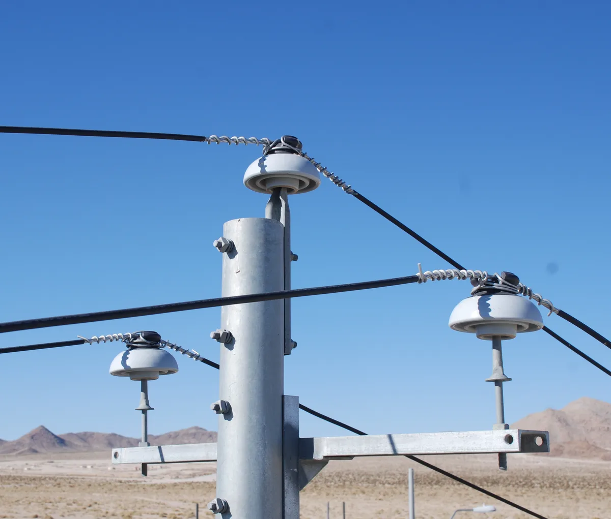
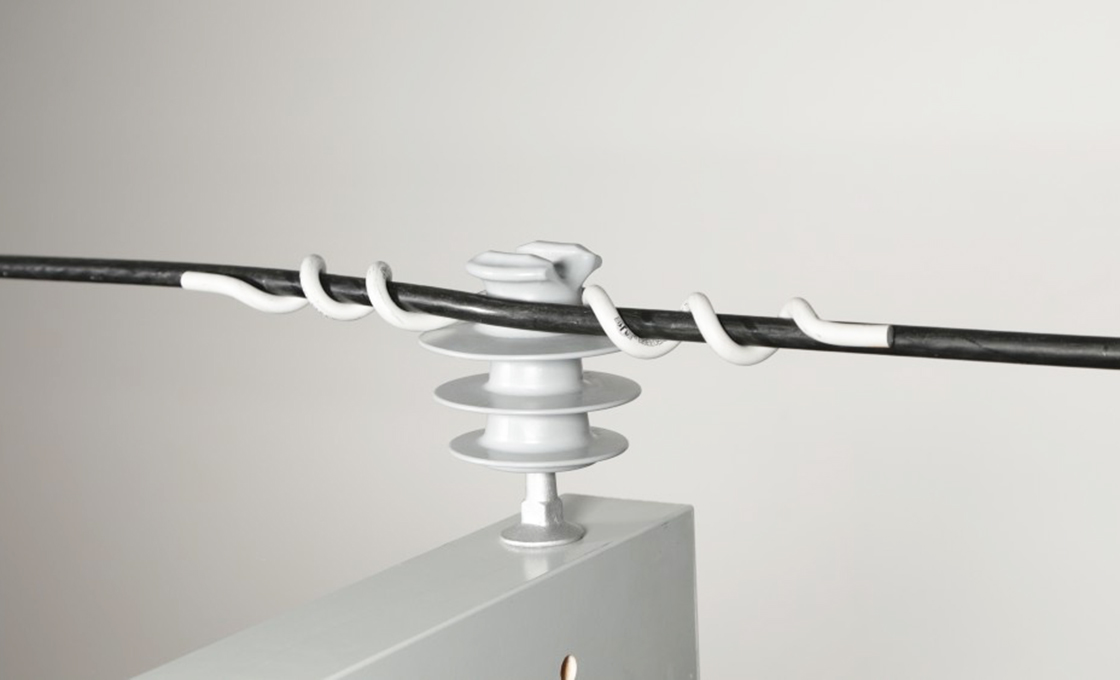
Three families of tie hold conductors on pin-type units. Hand ties are soft wire wound around the neck and over the conductor by the lineman. Factory-formed preformed ties arrive helixed to shape. Top ties close over the conductor in the top groove, while side ties wrap the neck and seat the conductor against the side groove.
Fit is exact, not approximate. Tie makers size each catalog number to the insulator neck and the conductor diameter, and the last letter of a formed-tie catalog name denotes the neck it fits. Distribution ties suit ANSI C29.5 interchangeable headstyle insulators, carry a neoprene tie tube as a cushion, and suit AAC, AAAC and ACSR conductors.
| Tie family | Where it seats | Verify on patrol |
|---|---|---|
| Hand tie | Soft wire wound into the groove | Wraps tight, no unwound ends, wire unbroken |
| Top tie (formed) | Closes over conductor in top groove | Neck letter matches, tube intact, no strand gaps |
| Side tie (formed) | Wraps neck, seats conductor in side groove | Conductor centered, tube not kinked |
| Spool tie | Spool insulators on secondary racks | Same tight-wrap and tube checks |
Formed ties also outlast hand ties where a span moves. Manufacturers state plainly that formed ties are superior to hand ties in vibration-prone areas. They may also be applied over armor rods or line guards where conductor surfaces already show wear. In our view, that one sentence should drive every re-tie decision on windy circuits.
Reading Tie Wire Wear in the Field
When the wind picks up, a healthy seat stays quiet. A conductor that rocks in its groove announces movement. So do tie turns that have unwound by a wrap, or polished fretting marks where tie meets conductor. Maintenance can still correct all of these cheaply from the next truck roll.
Read the tie in three places. At the conductor entry, a mis-sized tie either pinches the strand or leaves play. Around the neck, loose turns let the insulator work against the wire with every sway. At the seat, the conductor should sit centered, with the tie tube present and uncrushed, because the tube is the cushion between metal and metal.
Material matching matters as much as size. Formed ties are catalogued for compatibility with AAC, AAAC and ACSR conductors, and each number encodes the neck letter and the conductor diameter range it serves. A tie borrowed from another conductor family during a shortage never seats the same way twice, so order by catalog number rather than by eye.
Sharp geometry multiplies the damage. The PLP insulator-fit catalog warns that a sharp transition between the top and side grooves forces tie wire to bend over a fulcrum. That concentrates stress on both the tie and the insulator. It also notes that long saddles are especially hazardous to soft hand-tie wire. A groove that chews through ties is a geometry problem, not a tie problem.
Neck and Groove Checks That Take Seconds
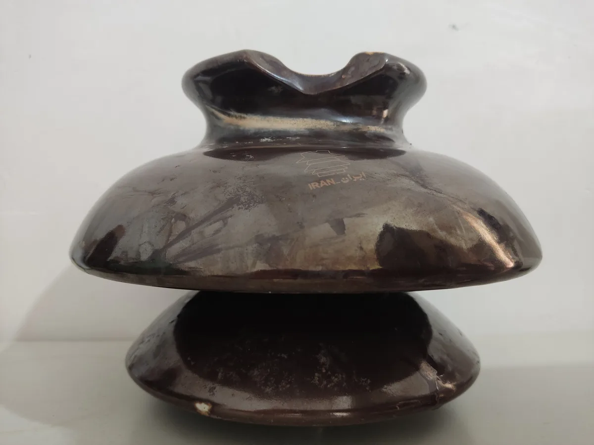
Every interchangeable pin insulator head follows ANSI C29 dimensions, and the numbers are small enough to remember. Neck diameters run 2-1/4 inches on a C-neck, 2-7/8 on an F, 3-1/2 on a J and 4 on a K. The same designation fixes minimum top and side groove radii, the maximum shoulder diameter and the vertical spacing between grooves.
Those dimensions decide which tie fits and the largest conductor the groove may carry, so one mismatched replacement insulator silently corrupts the whole seat. Polymer units do not escape the system. Polymer C and F-neck tie-top insulators at 15 and 35 kV are designed to match the same ANSI C29 head dimensions as porcelain, so they accept the same formed ties.
Trial-fit before committing a batch. Tie manufacturers recommend a thorough review of insulator size, shape and geometry, with trial fits, before full-scale field installation. A minute at the truck prevents a season of fretting at the top of the pole, which is the cheapest form of composite pin insulator maintenance there is.
Pins, Studs, and Clamps: The Hidden Load Path
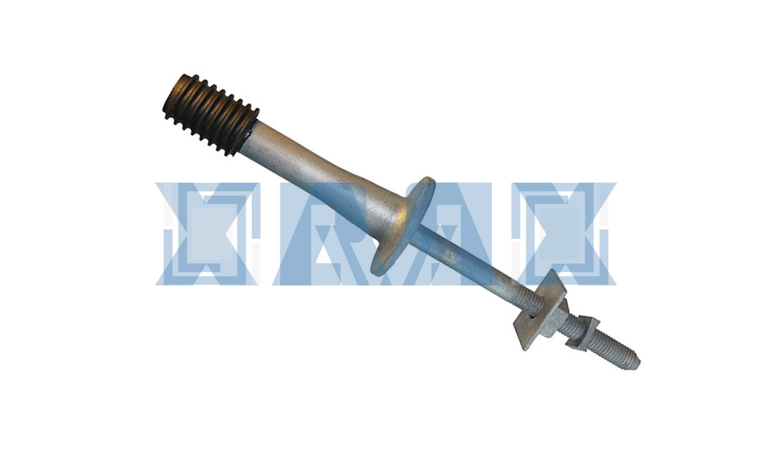
Under every pin insulator sits the part nobody photographs. Pole-top pins carry the insulator on a flange bolted to the pole, and a ductile iron unit of this type carries a 2,000 pound minimum ultimate strength. Crossarm pins use the standard 1-inch or 1-3/8-inch insulator threads in galvanized steel to ASTM A153, or clamp around the timber with a wide base that spreads load without drilling.
Field checks follow the load path. A pin shank that has bent tilts the groove above it. Stripped or deformed threads let the insulator rock. A missing nut or lockwasher hands the rest of the job to gravity. On clamp-type pins, confirm the carriage bolts are tight and the raised projections on the clamp plate still bite the crossarm face.
Thread material earns its own glance. Nylon insulator threads on modern pins meet the same ANSI dimensional requirements while resisting impact better than lead. They also remove the handling and disposal concerns that lead threads carried. The square wrenching shoulder above the base rotates the insulator groove into line, so re-check orientation after any pole work.
What a Leaning Insulator Tells You
A pin insulator that leans is reporting on its base. The housing can look pristine while a bent pin, a loose clamp or a worn bolt hole throws the groove out of plane. The conductor then rides one edge of its seat, the tie fatigues on one side, and the next storm collects the difference.
Treat lean as a chain of evidence: confirm the housing is sound, then work down through the tie and the pin seat before condemning the insulator itself. Most leaning units get re-pinned, not replaced, and the repair takes less hardware than one emergency callout. Photographing the seat during each visit also builds a wear history that no single climb can match.
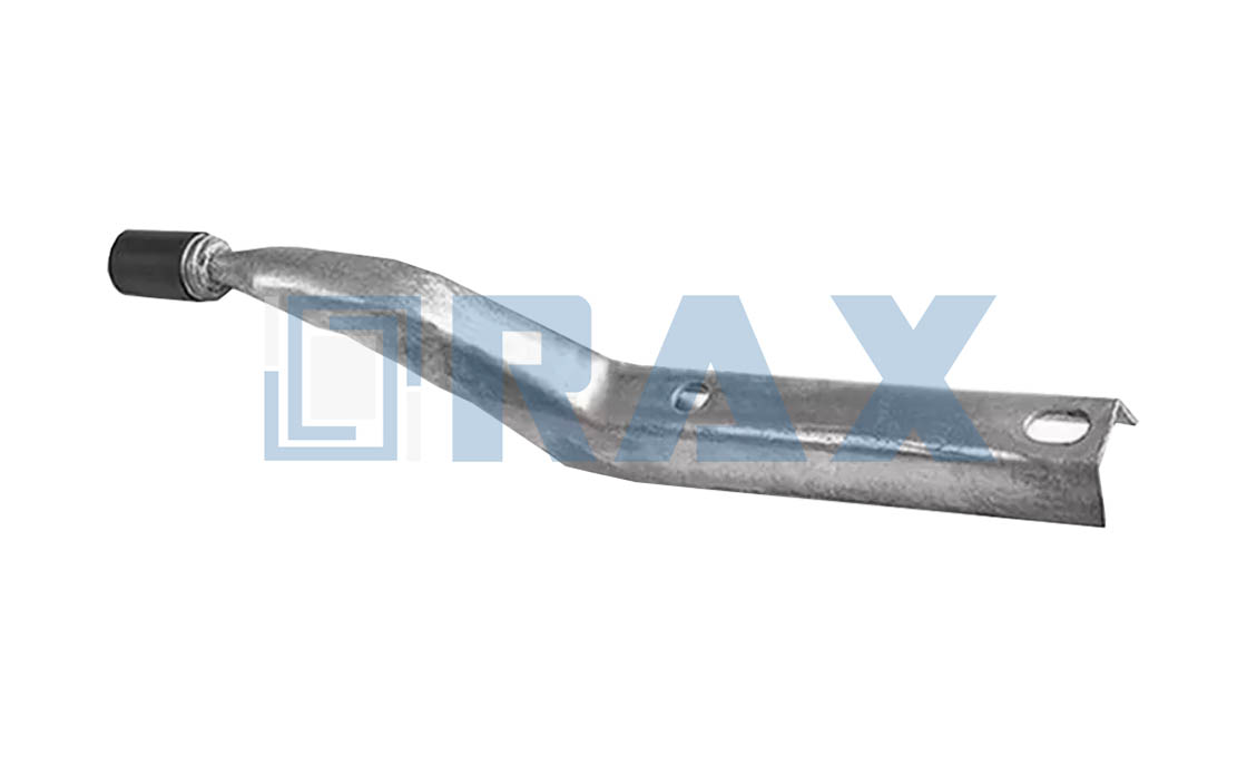
Pin Insulators Versus Suspension Strings
Maintenance programs written for suspension hardware do not transfer cleanly to pin-type circuits. A suspension string hangs from the structure, grades voltage across discs in series from 69 kV upward, and lets crews swap an individual failed unit without disassembling the string. Its inspection world is string hardware, links and corona rings.
A pin insulator is one rigid part at distribution voltage, so there is no string to grade and no socket to inspect. Composite pin insulator maintenance lives or dies on the tie, the groove and the pin, alongside the shed and housing checks every composite unit needs. For housing defects, UV and infrared diagnostics and removal criteria, the housing-focused companion guide covers that half of the job.
The spares list differs as well. A string crew stocks discs, links and corona hardware by voltage. A distribution crew stocks ties by neck letter, pins by thread size and a handful of clamp kits with their nuts and lockwashers. Budgeting seat hardware as its own line item keeps the right parts on the truck. Composite pin insulator maintenance then pays for itself one avoided climb at a time.
Fitting Support Checks Into Existing Rounds
Distribution circuits see people. Vegetation crews, meter readers and switching teams pass the same poles far more often than any inspection program reaches a transmission corridor, and seat checks should borrow that traffic. A three-point look, tie tight, groove centered, pin plumb, takes under a minute per structure from the ground with binoculars.
In our experience, the crews that close the most defects carry the fix with them. That means formed ties in the neck letters and conductor sizes the circuit uses, spare tie tubes, a few pins and the clamp hardware kit. A loose tie that waits three weeks for parts is a failure in waiting.
Re-Tie, Re-Pin, or Replace the Unit
Every seat defect resolves into one of three actions, and the cheapest usually wins. Decide from the ground, stage the parts, then climb once.
| Finding | Likely cause | Field action |
|---|---|---|
| Tie loose or unwound, seat centered | Vibration or settling | Re-tie with correct-size formed tie and new tube |
| Tie broken, conductor sound | Fatigue or sharp groove edge | Re-tie; inspect groove transition for the fulcrum effect |
| Conductor worn at the seat | Movement under a loose tie | Apply armor rods or line guard under the formed tie |
| Insulator leans or rocks | Bent pin, loose clamp, worn thread | Re-pin or re-clamp with new hardware |
| Groove chipped or shoulder broken | Geometry now hostile to any tie | Replace the unit with a matching neck |
A tie holds the conductor the way you lace a boot: tension from both sides, or it walks loose. Match the neck, respect the tube, and the decision matrix above collapses into routine.
Maintain the Seat, Not Just the Shed
The sheds on a composite unit age slowly and honestly. The seat ages fast and quietly, which is why composite pin insulator maintenance should begin with the tie, the groove and the pin underneath. Keep the neck letter matched, the tie formed and tubed, the pin plumb and the clamp biting, and the silicone above usually takes care of itself.
RaxPower supplies pin insulators, insulator pins and formed wire ties as one compatible program. The overhead line insulator range and the formed wire tie range cover both halves of the seat, from pole-top flange to tie tube.
عازل مثبت على العمود يمسك بالمواسير الرأسية على مسافة ثابتة من سطح العمود، مما يحمي الكابلات ويحافظ على الفصل عن الموصلات والمعدات الأخرى.
Do composite pin insulators need different tie wires?
No. Tie fit is governed by ANSI C29 head dimensions, not by housing material. Polymer C and F-neck insulators are built to the same neck and groove specifications as porcelain, so the same formed ties apply.
How do you match a replacement tie to an insulator?
Read the insulator neck letter first, then the conductor size. Catalog tables map each neck, from C at 2-1/4 inches to K at 4 inches, to a tie whose conductor diameter range must include your conductor.
Can a worn groove be re-tied, or must the unit be replaced?
Minor seat wear re-ties cleanly with a correct-size formed tie. Chipped shoulders or a sharp top-to-side transition bend ties over a fulcrum, so replace the insulator, because geometry, not the tie, is failing.
When should a hand tie be upgraded to a formed tie?
On vibration-prone spans. Manufacturers state that formed ties outperform hand ties there, and formed ties can be applied over armor rods or line guards where conductors already show wear.
What spare support hardware should a crew carry?
Formed ties in the neck letters and conductor sizes the circuit uses, spare tie tubes, a few 1-inch and 1-3/8-inch pins, and clamp hardware with nuts and lockwashers.