
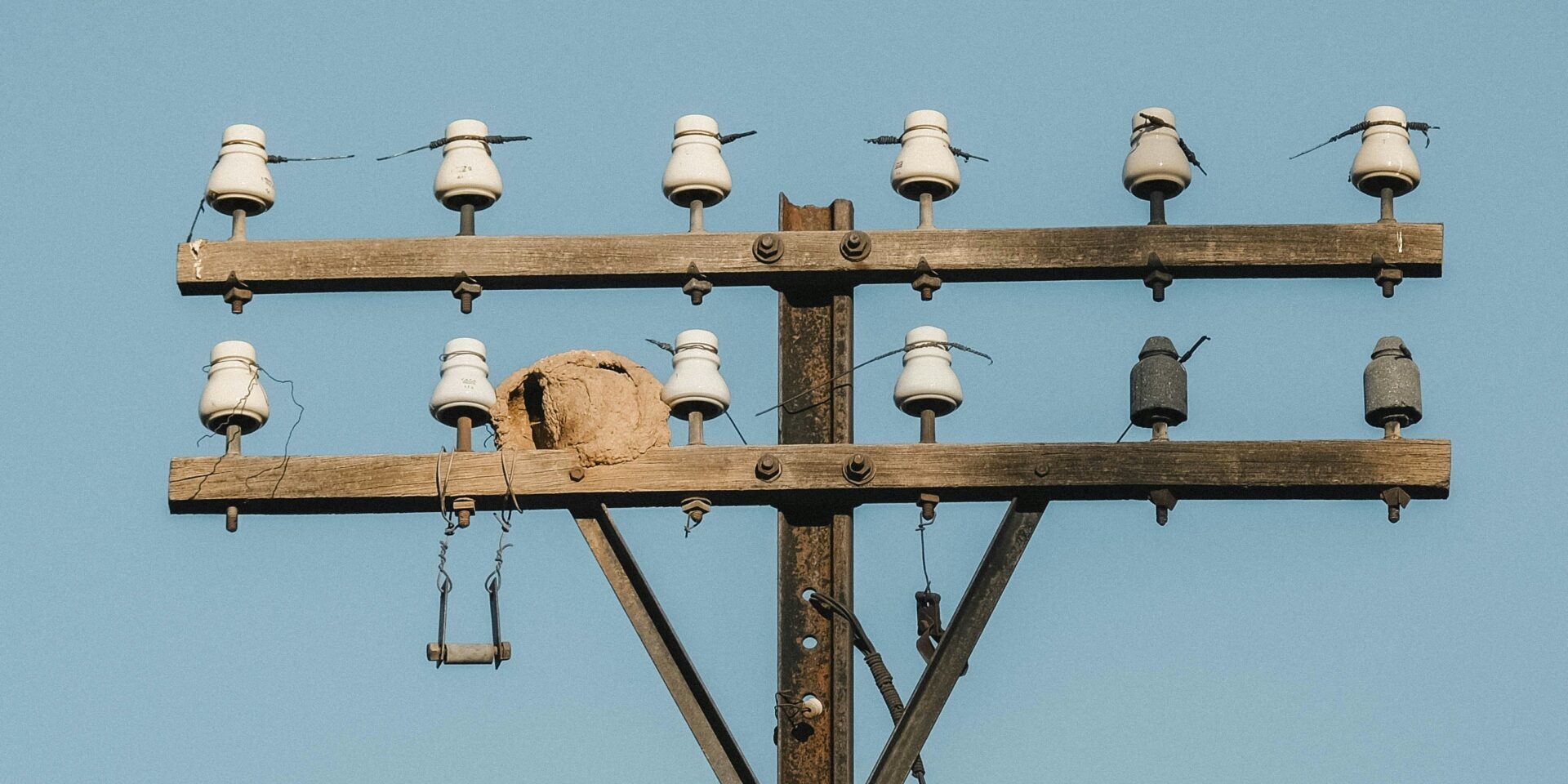
Definir as especificações corretas para isoladores de poste 132 kV exige atenção rigorosa aos detalhes dimensionais. Unidades compósitas padrão para esta classe de tensão geralmente exigem uma altura de montagem de 1245±20mm, mantendo um mínimo distância de fuga de 3200mm para lidar eficazmente com os níveis de poluição. Estabelecer esses números corretamente no papel não garante que cheguem ao canteiro de obras dessa forma. Na Rax Power, nossos dados internos de qualidade mostram que a verificação rigorosa de tolerâncias é a única maneira confiável de evitar incompatibilidades de montagem. Este guia esclarece as tolerâncias críticas de interface definidas pelas normas IEC e ANSI, focando especificamente nas diferenças de estabilidade dimensional entre núcleos cerâmicos e compósitos.
Você precisa saber onde um fabricante pode reduzir custos sem arriscar falhas e onde ele absolutamente não pode. Analisamos os protocolos de teste específicos que verificam o desvio dimensional a longo prazo sob ciclagem térmica e carga mecânica. Ao compreender essas nuances, você protege o cronograma do seu projeto dos atrasos de retrabalho causados por equipamentos que não se encaixam.
Conformidade com Normas Dimensionais IEC e ANSI
O erro mais caro nas compras globais é assumir que as normas IEC e ANSI são traduções intercambiáveis, em vez de filosofias de engenharia distintas.
Marcos Normativos para Sistemas 132 kV
Navegar pelas especificações de isoladores 132 kV requer compreender que IEC e ANSI operam sobre arquiteturas de documentação fundamentalmente diferentes. A abordagem IEC é modular: você deve consultar a norma de ensaio horizontal IEC 60383 para métodos de teste, e então consultar normas específicas do produto, como IEC 60720 (isolador de poste para linhas) ou IEC 60168 (isolador de poste para subestações), para dimensões e classificações. A ANSI adota uma abordagem consolidada por meio da série C29 — especificamente ANSI C29.7 para isoladores cerâmicos de poste para linhas — onde definições do produto, ensaios e dimensões estão consolidados em um único documento.
Essa diferença estrutural cria um risco de conformidade durante a avaliação de propostas. Se uma empresa de EPC especificar ‘conformidade com IEC 60383’ sem citar a norma específica do produto para as dimensões da interface, os fabricantes não terão uma referência normativa completa para verificar o ajuste geométrico. Para sistemas 132 kV especificamente, certifique-se de que a especificação vincule explicitamente o método de ensaio (IEC 60383) à norma do produto (IEC 60168 ou 61952) e ao guia de seleção ambiental IEC 60815 para evitar entregáveis técnicos ambíguos.
Tolerâncias Dimensionais: Precisão Métrica vs. Encaixe Legado
Embora as tabelas de dados forneçam os valores nominais, a realidade da engenharia está na filosofia de tolerância. As normas ANSI frequentemente carregam o legado das medidas imperiais, resultando em tolerâncias de interface historicamente determinadas por modelos específicos de hardware de concessionárias. As tolerâncias IEC, sendo estritamente métricas, podem às vezes parecer mais amplas ou generalizadas, transferindo o ônus da verificação do ‘encaixe’ para a conformidade do fabricante com a norma do produto, em vez de uma ferramenta de medição específica.
Classes de Poluição: A Lacuna de Interpretação
Creepage distance is defined mathematically, but the Pollution Class (I to IV) assigned to a site is a subjective engineering judgment. IEC 60815 provides the selection methodology, but a ‘Heavy Pollution’ classification in a coastal region with salt fog differs physically from an industrial zone with cement dust. The ‘gap’ in standard interpretation arises here: two engineers can look at the same site, validly apply IEC 60815, and arrive at different creepage requirements based on their risk appetite for cleaning schedules.
This ambiguity directly impacts the insulator’s overall geometry and diameter. Over-specifying the pollution class inflates the cost and size unnecessarily; under-specifying it invites flashover events. To bridge this gap, do not rely solely on the standard class label. Instead, specify the minimum Specific Creepage Distance (mm/kV) required in the technical schedule. This removes the subjectivity of the class definition and locks the manufacturer into a precise dimensional target.
| Component Category | IEC Standard Scope | ANSI / NEMA Standard Scope | Compliance Mapping | Critical Note |
|---|---|---|---|---|
| Standard Structure | Layered System: Horizontal test standards (IEC 60383) + Specific product standards (IEC 60168, 61952) | Bundled System: Product type, ratings, and tests in single type-specific documents (C29.x series) | Cross-region procurement requires mapping both axes, not just translating part numbers | IEC splits product definition from test method; ANSI bundles them into one document set |
| Ceramic Line Post | IEC 60720 (Product) + IEC 60383-2 (Test Reference) | ANSI C29.7 (High-Voltage Line Post) | IEC 60720 maps to C29.7 for ceramic line post dimensional & mechanical specs | Verify specific edition cited in project specification as mapping is inferred for EPC bids |
| Ceramic Station Post | IEC 60168 (Contains both product specs and test references) | ANSI C29.9 (Station Post) | IEC 60168 is the direct functional equivalent to C29.9 for substation posts | IEC 60168 is self-contained for testing, unlike other IEC product families |
| Composite Line Post | IEC 61952 | ANSI C29.17 / C29.18 (Composite Line Post) | Direct mapping between IEC 61952 and ANSI C29.17/18 family | Critical for specifying polymer hardware in different grid infrastructures |
| Composite Station Post | IEC 62231 | ANSI C29.19 (Station Post Composite) | IEC 62231 aligns with C29.19 for composite station insulation | Ensure creepage requirements match local pollution classes (IEC 60815 vs IEEE) |
| Creepage & Pollution | IEC 60815-1/-2/-3 (Selection for polluted environments) | IEEE Std 4 / IEEE 1313 (Referenced within C29) | IEC provides a dedicated standard series; ANSI references IEEE for methodology | Creepage distance calculation methods vary significantly between families |
| Voltage Test Criteria | Withstand Values (Power-frequency wet, Lightning impulse) | Flashover Values (Critical Impulse Flashover – CFO) | Not one-to-one; CFO (50% flashover) != Withstand (Guaranteed floor) | A unit passing ANSI CFO at X kV may fail IEC Withstand at X kV |
| Mechanical Rating | SML (Specified Mechanical Load) / SFL (Specified Failing Load) | M&E (Mechanical and Electrical) Strength | M&E rates load at 1 min under combined voltage; SML/SFL focuses on load capacity | Load duration definitions differ; verify test durations match project specs |

Altura Nominal e Diâmetro do Núcleo
Nominal height and core diameter are the non-negotiable baselines for 132 kV structural integrity. Exceeding standard tolerances by even millimeters compromises safety clearance and mechanical load ratings.
Diâmetro do Núcleo: A Coluna Vertebral da Integridade Mecânica
Mechanical performance in 132 kV solid-core post insulators hinges directly on the core diameter. For a unit requiring a standard 12.5 kN bending strength, the core diameter is the primary determinant of performance. It is not a variable to be trimmed for cost savings; it is a fixed non-negotiable. A deviation in core diameter directly alters the section modulus, meaning a reduction of just a few millimeters can significantly lower the unit’s ability to withstand cantilever loads and torsional stress during high-wind events. Unlike competitors who may rely on casting—a process prone to porosity and dimensional inconsistency—we utilize hot-forging technology. This ensures the internal structure is dense and the diameter remains uniform from the base to the top cap, eliminating the weak points found in lower-quality alternatives.
Altura Nominal e Compensação Térmica
Nominal height defines the critical creepage distance and phase-to-ground clearance. However, buyers often fail to account for thermal drift when specifying height. Ceramic materials have a low coefficient of thermal expansion, but composite insulators can exhibit creep or expansion over time, especially in the extreme temperature variances seen in markets like Russia or Southeast Asia. To prevent installation failures, the specified nominal height must account for the galvanizing thickness on end fittings. We apply a hot-dip galvanizing process compliant with ISO 1461, ensuring a mean coating thickness exceeding 85 microns. While this adds superior corrosion resistance, it adds physical material dimensions. Our engineering team factors this coating depth into the initial design phase, ensuring the final assembled unit meets the exact electrical clearance requirements without the need for field shimming.
Controle de Fabricação: O Padrão Rax Power
Achieving theoretical dimensions on a CAD drawing is easy; holding them in mass production is where the supply chain often fails. We apply the same rigorous tolerance standards used in our steel cross arms—where we maintain a strict 1mm tolerance—to our insulator lines. Our automated machinery guarantees that the first unit and the thousandth unit are dimensionally identical.
- Double-Review QC Protocol: Every unit undergoes two distinct dimensional inspections before packaging. A dedicated 10-person QC team monitors critical interfaces to ensure mounting holes align perfectly with substation structures.
- In-House Gauge Testing: We conduct rigorous gauge testing per IEC 120 standards. This verifies that the core diameter and spacing remain within strict safety margins, even under thermal load simulation.
- SGS Verification: Our dimensional control protocols are not internal secrets but verified standards. All processes and products are SGS tested and verified, providing the traceability required for high-tier utility tenders in South America and Europe.
Distância de Vazamento e Espaçamento de Abas
Effective pollution performance relies not just on total creepage distance, but on optimized shed geometry that maximizes self-cleaning while maintaining mechanical integrity.
A Lógica de Engenharia por Trás do Espaçamento de Abas
Specifying creepage distance is more than just calculating a total length; it requires precise geometry to ensure the insulator can shed contaminants effectively. In high-pollution environments, such as coastal areas or industrial zones, a simple increase in length is insufficient if the shed spacing allows for pollution bridging under wet conditions. A common pain point for procurement teams is receiving insulators that technically meet the minimum millimeter ratings but fail in the field due to poor aerodynamic profiles that encourage dirt accumulation on the lower surfaces.
Otimização da Geometria para Ambientes Severos
To counteract flashovers, the ratio between shed spacing and projection becomes a critical factor. An open aerodynamic profile is essential to ensure natural wind cleaning and prevent the formation of continuous conductive paths. We have observed that inconsistent molding in manual production often leads to uneven spacing, creating “dead zones” where pollution builds up. To eliminate this risk, we utilize automated molding systems that guarantee uniform geometry across every batch. This ensures that the self-cleaning capabilities designed in the lab translate directly to field performance.
Verificação e Controle de Qualidade
Visual inspection alone is insufficient to validate complex profiles. At our facility, rigorous dimensional gauge testing is applied to every production run to verify that the alternating sheds meet the strict specifications required for heavy pollution standards. Our 10-person QC team performs a double-review process, rejecting any unit where the shed spacing deviates from the design parameters. This strict adherence to geometric consistency is why our insulators maintain hydrophobicity transfer capabilities and withstand the specific demands of utility tenders in regions like South America and Southeast Asia.
| Parâmetro | 132 kV Industry Standard | Rax Power Quality Assurance | Key Benefit |
|---|---|---|---|
| Specific Creepage Distance | ≥ 31 mm/kV (Total ≥ 4495 mm) | Design exceeds Class IV pollution standards; SGS verified | Prevents flashovers in coastal/saline environments |
| Shed Profile & Ratio | Open aerodynamic alternating sheds; S/P ratio ≥ 1 | Automated precision molding ensures consistent geometry | Enhances self-cleaning and hydrophobicity transfer |
| Dry Arcing Distance | Minimum 1.5 m | In-house testing per IEC 120 standards | Guarantees reliability during switching surges |
| Connecting Length | 1.48 ± 0.02 m | 100% double-review process by dedicated QC team | Seamless fit with mounting hardware and cross-arms |
| Insulation Length | Minimum 1.2 m | Rigorous dimensional gauge testing | Ensures safe isolation of live components |
Tolerâncias de Interface dos Acoplamentos de Extremidade
To prevent assembly blocking, interface dimensions must account for the mean zinc coating thickness exceeding 85 microns required by ISO 1461.
The most frequent failure mode in pole line hardware assembly is not material failure; it is the inability to assemble components on site due to tolerance stack-up. B2B buyers often face a scenario where standard U-bolts will not pass through pole band holes, or clevis pins bind in insulator caps. This typically happens when manufacturers drill to the nominal steel size and ignore the dimensional build-up added by the galvanizing layer. This oversight creates immediate installation delays, forcing crews to ream holes or use hammers—actions that compromise the integrity of the corrosion protection.
At our facility, we treat galvanizing as a critical variable in our tolerance equation, not a secondary coating process. We strictly adhere to ISO 1461 hot-dip galvanizing standards, which results in a mean coating thickness exceeding 85 microns. To ensure 100% compatibility, our automated production lines pre-calibrate drilling dimensions to account for this specific zinc thickness. We apply a “reverse tolerance” strategy: if the final assembly requires a 16mm bolt, we drill the raw material significantly larger so that after the 85-micron coating is applied, the clearance is perfect. This ensures that when your installation crew arrives, the hardware slips together without force or modification.
Protocolos Técnicos de Tolerância
- Coating Compensation: All drilling and boring dimensions are offset to accommodate the mean zinc thickness of over 85 microns, ensuring post-galvanized interface accuracy.
- Hot-Forging Consistency: By employing hot-forging rather than casting for critical interfaces, we minimize shrinkage and warping, delivering superior dimensional stability compared to traditional sand-cast methods.
Como você verifica se as dimensões da interface estão de acordo com as normas de isoladores?
We do not rely solely on calipers. Our in-house QC team performs physical gauge testing per IEC 120 standards on every batch. This verifies that the curvature, ball/socket dimensions, and pin clearances will mechanically lock with standard insulators before the goods leave the factory floor.
Resistência em Viga de Consola vs. Altura
Increasing mounting height linearly amplifies bending stress at the base, requiring a proportional increase in specified Cantilever Strength to maintain safety margins.
A Física da Alavanca em Sistemas 132 kV
Leverage mechanics dictate that increased mounting height amplifies the moment arm at the base. Consequently, even standard wind or conductor loads generate significantly higher bending stresses at the root. For 132 kV solid-core post insulators, this is not merely a theoretical concern but a critical safety factor. While standard specifications often list a nominal bending strength of 12.5 kN, real-world applications involving taller mounting configurations demand engineers calculate the specific moment load to verify that this rating provides a sufficient safety factor.
Consistência do Material sob Esforço
Height-induced stress exposes inconsistencies in manufacturing that might otherwise remain dormant at lower elevations. A taller insulator acts as a longer lever, magnifying any microscopic voids or uneven cementing within the end fittings. We address this by utilizing advanced hot-forging technology for our metal components rather than traditional casting. This method ensures the grain structure of the steel is continuous and aligned, offering superior toughness to handle the amplified leverage forces found in elevated 132 kV installations. Furthermore, our strict 1mm dimensional tolerance on steel cross arms ensures that the insulator is seated perfectly flat, preventing point-loading stresses that could compromise a taller unit.
Protocolos de Verificação para Aplicações de Alto Esforço
To guarantee performance across all specified heights, we implement a double-review process that goes beyond standard sampling. Every unit undergoes rigorous in-house load testing and gauge testing per IEC 120 standards before packaging. This protocol is crucial because a taller insulator failing under cantilever load poses a severe risk to grid stability.
- Rigorous destruction testing confirms that theoretical ratings align with physical performance limits. We validate the 12.5 kN bending rating and 3 kNm torsional strength through physical destruction tests on sample batches.
- End Fitting Security: Our automated crimping and assembly processes guarantee the bond between the porcelain core and metal flanges can withstand the increased leverage without creeping or loosening over time.
- SGS Certification: All processes are verified by SGS, providing third-party validation that our cantilever strength claims are accurate and reliable for high-stakes environments.

Espaçamento Centro a Centro de Montagem
In 132 kV transmission infrastructure, the mounting center-to-center spacing—the precise distance between the bolt holes on the support structure—is rarely given the attention it deserves during the procurement phase. Yet, this dimension is the single most critical factor in determining whether a project proceeds smoothly or stalls due to fitment issues. A deviation of just a few millimeters might seem negligible in a warehouse, but on a tensioned pole line, it forces installation crews to compromise the hardware’s integrity through field modifications. Buyers often settle for “standard” spacing without realizing that “standard” varies wildly between regions and manufacturers, creating a logistical nightmare when mixing and matching components from different suppliers.
Sensibilidade à Orientação e Distribuição de Carga
The impact of spacing tolerance is heavily dependent on the mounting orientation. For horizontal line post applications, which are common in 132 kV systems, the insulator acts as a cantilever beam. If the center-to-center spacing on the cross arm does not match the insulator’s base dimensions precisely, the mounting hardware is subjected to uneven shear stress. This misalignment creates a bending moment at the connection point that the hardware was not designed to withstand. While vertical mounting offers some forgiveness through gravity, horizontal configurations demand absolute precision. In our experience, the majority of hardware fatigue failures in horizontal installations can be traced back to initial spacing deviations exceeding 2mm.
Eliminação do Risco de “Encaixe à Força” com Automação
This is where we differentiate our manufacturing approach from the general market. We identified that inconsistent spacing in steel cross arms and pole brackets was a primary pain point for our B2B partners, leading to increased installation times and higher return rates. To solve this, we implemented fully automated production lines for our steel cross arms, ensuring a strict 1mm tolerance on all center-to-center dimensions. Unlike traditional manual fabrication methods, which are prone to human error and cumulative drift, our automated systems guarantee that every bracket leaving our factory matches the nominal drawing exactly.
- Zero-Field Modification: Our 1mm tolerance ensures that insulators bolt directly onto our cross arms without the need for shims, washers, or dangerous on-site drilling.
- Protected Structural Integrity: Exact spacing prevents point-loading on insulator end fittings, preserving the cement and preventing the micro-cracks that lead to premature failure.
- Bulk Consistency: For large-scale utility projects, our automated process guarantees that the 1,000th cross arm is identical to the first, eliminating the variability that plagues cast or loosely fabricated alternatives.
Tabelas de Folgas e Espaçamentos de Instalação
Clearance is the invisible insurance policy of the grid. Calculating for dry air is easy; calculating for dynamic conductor swing, wind loads, and maintenance tool arcs is where engineering precision separates a compliant line from a failing one.
Valores de folga entre fases e entre fase e terra
For 132 kV systems, statutory minimum clearances are non-negotiable safety baselines defined to prevent flashover under power frequency and switching surge conditions. While specific values vary slightly by regional code (IEC vs ANSI), industry standard baselines for 132 kV infrastructure typically require a minimum phase-to-ground distance of approximately 1,200 mm and a phase-to-phase spacing of at least 1,500 mm to account for overvoltage stress.
Distâncias mínimas de segurança para manutenção em linha viva
Beyond static clearance, engineers must design for the Minimum Approach Distance (MAD) required for hot-stick or bare-hand maintenance. For 132 kV lines, the MAD is typically calculated around 0.9 to 1.0 meters from the energized conductor. However, this is a theoretical minimum for the worker’s body; the structure must accommodate the additional reach of conductive tools (hot sticks), which can extend the required zone to 1.5 meters or more.
Impacto da orientação de montagem nos requisitos de folga
Mounting orientation fundamentally alters clearance physics. Vertical mounting is geometrically stable, but horizontal mounting (line post) introduces dynamic variables. When installed horizontally, the insulator acts as a cantilever beam. Under maximum wind load or ice weight, the conductor deflects downward and swings laterally. This ‘swing angle’ eats into your phase-to-ground and phase-to-phase margins.
This mechanical deflection means the initial electrical clearance must be oversized to preserve the safety gap at maximum deflection. In our production facility, we mitigate this risk at the hardware level. Because our steel cross arms are manufactured with an automated tolerance of just 1mm, we eliminate the ‘wobble’ or play often found in loosely fitted assemblies. This precision ensures that the initial positioning is millimeter-perfect, allowing you to reserve your entire safety margin for environmental factors rather than installation error.
Verificação da Qualidade e Deriva Dimensional
Passing the initial inspection guarantees today’s fit. Validating geometric stability over thermal cycles guarantees the fit 30 years from now.
Previsão de estabilidade do ciclo de vida para ciclagem térmica
Standard ceramic cores exhibit minimal thermal expansion, typically under 6 x 10⁻⁶/K, ensuring geometric stability across temperature fluctuations. The critical risk lies in the polymer interfaces of end fittings and the cementitious grout used to bond the core to the metal. Under repetitive thermal cycling—ranging from -40°C in northern climates to +80°C in direct sunlight—differential expansion rates can induce micro-cracking at the interface. This “dimensional drift” is often imperceptible during a standard 48-hour test run but accumulates over a 20-year service life, potentially compromising the mechanical cantilever strength.
We have observed through our long-term supply relationships in Russia that units subjected to extreme, rapid temperature shifts require a specific cement formulation. Standard mortar mixtures often degrade under these freeze-thaw cycles. We account for this by using sulfur cement or specialized epoxy compounds for high-voltage units destined for volatile environments, ensuring the interface remains rigid regardless of thermal stress.
Técnicas avançadas de medição para tolerâncias internas
Standard calipers verify external dimensions, yet they fail to detect critical internal tolerance stack-ups. The interface between the insulator core and the end fitting relies on precise internal clearances to maintain structural integrity. To verify this, advanced measurement must move beyond basic length checks.
- IEC 120 Gauge Testing: This is the non-negotiable standard for verifying interface dimensions. We utilize precision “Go/No-Go” gauges to check the ball, socket, and tongue dimensions of every end fitting. This ensures mechanical interchangeability and correct fit-up with hardware during assembly.
- Coordinate Measuring Machines (CMM): For custom ODM projects, we deploy CMMs to map the complex geometry of clevis and tongue interfaces, identifying deviations as small as 0.02mm that traditional calipers would miss.
- Ultrasonic Thickness Testing: This verifies the uniformity of the porcelain wall thickness, detecting eccentricity that could lead to weak points under high mechanical load.
Our quality protocol mandates a 100% double-review process. A dedicated 10-person QC team inspects every unit immediately after galvanizing and again before packaging. This redundancy catches the 0.5% of units that might pass a single automated visual scan but fail a tactile gauge test.
Efeitos da compensação de temperatura nas dimensões da interface
The interface dimensions of the end fitting are not static; they fluctuate with ambient temperature. Steel end fittings have a higher coefficient of thermal expansion than the ceramic core. During installation in high-temperature environments, the metal expands, potentially altering the engagement depth of the ball and socket or the pin-hole diameter.
Conclusão
Don’t just chase the lowest unit price. If the mounting spacing is off by even a few millimeters, your field crew loses hours adjusting brackets. Stick to IEC 60383 tolerances rigorously, especially for creepage distance in polluted areas. Ceramic offers better long-term dimensional stability than composites for rigid 132 kV bus supports, so choose material based on thermal cycling expectations. Precision now prevents expensive downtime later.
We treat dimension verification as a critical ROI factor, not just a paperwork step. Our 10-person QC team performs a rigorous double-review on every batch to guarantee those IEC tolerances are dead-on before shipping. Send us your specific mounting drawings or technical specs. We’ll run a free compatibility check to ensure the end fittings align perfectly with your existing hardware structure.
Perguntas Frequentes
Quais são as dimensões críticas de vazamento e espaçamento?
As dimensões críticas incluem a distância de fuga, que deve ser suficiente para evitar relâmpagos sob condições de poluição, e o diâmetro do núcleo para resistência mecânica. Os engenheiros também devem verificar a distância de arco a seco para garantir que as folgas de segurança elétrica sejam atendidas. Essas medições devem estar em conformidade com as normas IEC para garantir desempenho confiável na transmissão de 132 kV.
Quais são as tolerâncias dimensionais padrão?
As tolerâncias padrão para isoladores de alta tensão são geralmente regidas por especificações da IEC para garantir ajuste universal e segurança. Tolerâncias mais rigorosas são cruciais para o hardware de conexão, pois mesmo pequenas variações podem causar tensões ou falhas na montagem. Os fabricantes frequentemente implementam sistemas automatizados para manter a consistência em grandes volumes de produção.
Estabilidade dimensional: cerâmica vs. compósito?
Ceramic insulators maintain rigid dimensional stability over decades, making them highly predictable under heavy mechanical loads and compression. Composite alternatives offer advantages in weight and vandalism resistance but require strict monitoring for creep and long-term material degradation. Selection should be based on specific environmental conditions and the mechanical stress dynamics of the 132 kV line.
Como o ambiente afeta as dimensões?
Environmental factors such as extreme thermal cycling can influence material expansion and contraction, potentially affecting mounting dimensions over time. UV exposure and industrial pollution may degrade composite housing, altering the effective creepage distance. Selecting materials with high thermal stability and protective coatings helps maintain dimensional integrity throughout the insulator’s service life.
Como garantir o encaixe correto de instalação?
Garantir o ajuste correto da instalação exige o cotejamento das dimensões da interface do isolador com os desenhos dos componentes de montagem que acompanham o isolador. Recomenda-se a realização de testes de medição antes da instalação para detectar eventuais desvios dimensionais que possam dificultar a montagem. Um encaixe preciso evita uma distribuição desigual das tensões nos fixadores e no isolador durante a operação.