
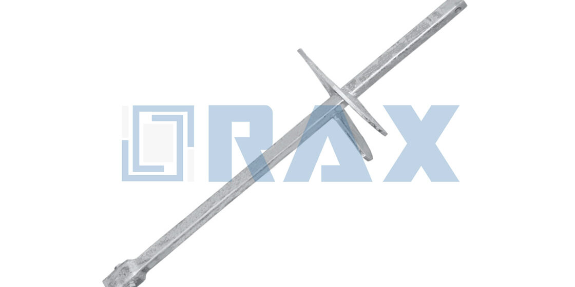
Eine Spannklemme ist ein Bauteil, das ein Kabel oder einen unter axialer Belastung stehenden Leiter umgreift und verankert, ihn unter Spannung hält und unbeweglich fixiert, ohne zu rutschen. Doch nicht jede Art von Ankerspannklemme bewältigt diese mechanische Anforderung unter Freilandbedingungen auf dieselbe Weise. Man muss über die grundlegende Katalogdefinition hinausblicken, um zu verstehen, wie spezifische Mechanismen über eine Nutzungsdauer von zwanzig Jahren auf Wind, Eis und Vibrationen reagieren.
Branchenstandards schreiben vor, dass eine ordnungsgemäß spezifizierte Totendreherklemme eine Griffkraft von mindestens 90 % der Nennbruchfestigkeit des Leiters erbringen muss. Das Erreichen dieser Schwelle erfordert, dass Klemmkörper und Keilmaterial exakt auf Ihre Anwendung abgestimmt werden, unabhängig davon, ob Sie ADSS-Faser oder ACSR-Leiter. einsetzen. Diese Analyse vergleicht Keil-, Schraub- und vormontierte Systeme, um zu zeigen, welche Bauarten bei hohen Spannweiten-Kreuzungen am besten bestehen und welche sich für die schnellste Installation bei Netzmodernisierungen eignen. Wir untersuchen zudem, wie Materialentscheidungen wie Aluminiumlegierung versus verzinkter Stahl die Korrosionsbeständigkeit in Küstenzonen beeinflussen.
Die Auswahl der richtigen Ausrüstung verhindert das Durchrutschen und Leiterschäden, die häufig zu Verstößen gegen Ausschreibungsvorgaben führen. Sie schließen diesen Artikel mit einem klaren Rahmen zur Priorisierung von Tragfähigkeitsbewertungen und Umweltschutz ab, ohne dabei die Installationseffizienz opfern zu müssen.
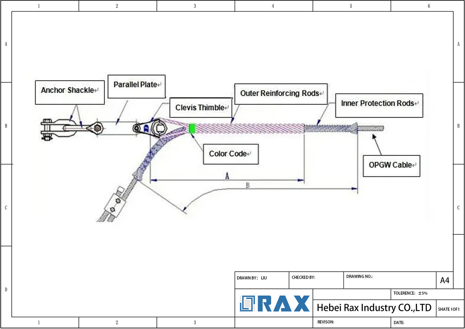
So wählen Sie die richtige Ankerspannklemme
Tragfähigkeitsbewertungen nach Ankerart
Die Auswahl einer Ankerspannklemme ausschließlich basierend auf dem Leiterdurchmesser ist ein häufiger Fehler, der zu Feldausfällen führt. Die kritische Kenngröße ist die Rutschlastbewertung im Verhältnis zur Nennbruchfestigkeit (RBS) des Leiters. Für B2B-Beschaffungen müssen Sie überprüfen, ob die Klemme mindestens 95 % der RTS (Nennzugfestigkeit) des Leiters ohne Durchrutschen halten kann, insbesondere unter dynamischen Wind- oder Eisbelastungsbedingungen. Verschiedene Ankerarten verhalten sich mechanisch unterschiedlich: Keiltypen verlassen sich auf zunehmende Reibung bei steigender Belastung, geschraubte Typen hängen von einem konstanten Anzugsmoment ab, und formstabile schraubenförmige Griffe verteilen die Belastung über eine breitere Oberfläche.
Ingenieurhinweis: Gehen Sie niemals davon aus, dass die im Katalog angegebene “Maximale Betriebslast” gleich der Rutschlast ist. Fordern Sie stets den spezifischen “Rutschprüfbericht” gemäß IEC-Normen ein, um Sicherheitsreserven zu gewährleisten.
Nach unserer Fertigungserfahrung hat die Varianz in der Rohmaterialkonsistenz erheblichen Einfluss auf die Griffleistung. Wir führen rigorose interne Last- und Messprüfungen gemäß IEC 120 durch, um jede Charge zu validieren. Unsere Daten bestätigen, dass unsere Griffkraft durch präzise hot-forging und strenge Maßkontrolle konsistent mehr als 90 % der Nennbruchfestigkeit des Leiters überschreitet. Diese hohe Rückhaltestärke ist für kritische Infrastruktur wie ADSS/OPGW-Spannweiten, wo ein einziger Rutschvorfall die Faserverbindung unterbrechen und massive Ausfallkosten verursachen kann, nicht verhandelbar.
- Keiltyp-Klemmen: Ideal für Hochkraftanwendungen; der selbstverriegelnde Mechanismus erhöht den Halt, wenn die Spannung steigt, erfordert jedoch eine präzise Außendurchmesser-Anpassung.
- Geschraubte Typ-Klemmen: Geeignet für geringere Spannung oder ABC-Kabeln; die Leistung hängt stark von der Aufrechterhaltung des Installationsmoments über die Zeit ab.
- Formstabile schraubenförmige Griffe: Bieten den höchsten Ermüdungswiderstand und verteilten Druck, wesentlich für großspannweiten Flussquerungen oder vibrationsanfällige Bereiche.
Faktoren der umweltbedingten Korrosionsbeständigkeit
Korrosion ist der stille Tod der Ankerlebensdauer. Bei der Bewertung von Klemmen betrachten Käufer oft das Grundmaterial – Stahl versus Aluminiumlegierung – übersehen jedoch die Beschichtungstechnologie. In Küsten- oder Industriezonen mit hoher Salinität oder Verschmutzung versagt standardmäßige elektroverzinkung oft innerhalb weniger Jahre, was zu fest sitzenden Muttern und beeinträchtigter struktureller Integrität führt. Der Industrie-Benchmark für zuverlässigen, langfristigen Einsatz in rauen Umgebungen ist ISO 1461 konform hot-dip galvanizing.
We strictly adhere to ISO 1461 standards, ensuring a mean coating thickness that exceeds 85 microns. This robust barrier provides decades of protection against red rust. Unlike competitors who may settle for thinner coatings to reduce costs, our automated galvanizing process ensures a smooth, bright finish that is free from rough slag or drips—imperfections that can create initiation points for corrosion or damage the cable jacket during installation. For projects in Russia or South America where environmental stressors are extreme, this coating depth is the difference between a 10-year asset and a 30-year asset.
Anzugsmomentspezifikationen für Klemmen
The installation phase is where most clamp failures originate, specifically regarding torque application. Over-tightening a bolted clamp or applying excessive torque to a wedge-type housing can crush the conductor’s core or damage the protective jacket of ADSS cables, leading to premature fatigue failure. Conversely, under-tightening results in slip under load. Precision manufacturing of the clamp body itself plays a pivotal role here; if the housing dimensions are inconsistent, the pressure distribution will be uneven regardless of the technician’s skill.
Our automated manufacturing lines enforce a strict ±1mm tolerance on all critical dimensions. This precision ensures that when the installation torque is applied, the force is distributed symmetrically across the cable, eliminating hotspots that cause degradation. We supply detailed torque specifications (usually measured in Nm) matched to the specific hardware grade (e.g., 4.8, 6.8, or 8.8) for every batch. Adhering to these values, verified by our dual-stage QC process, guarantees that the clamp’s mechanical holding power is fully realized without compromising the physical integrity of the conductor.
- Torque Wrench Calibration: Ensure field tools are calibrated; a 20% variance in torque can translate to a 40% variance in clamping pressure.
- Nyloc Nuts vs. Standard Nuts: For vibration-heavy lines, specify nylon-insert nuts to prevent back-off, but verify the nylon’s temperature rating matches the climate.
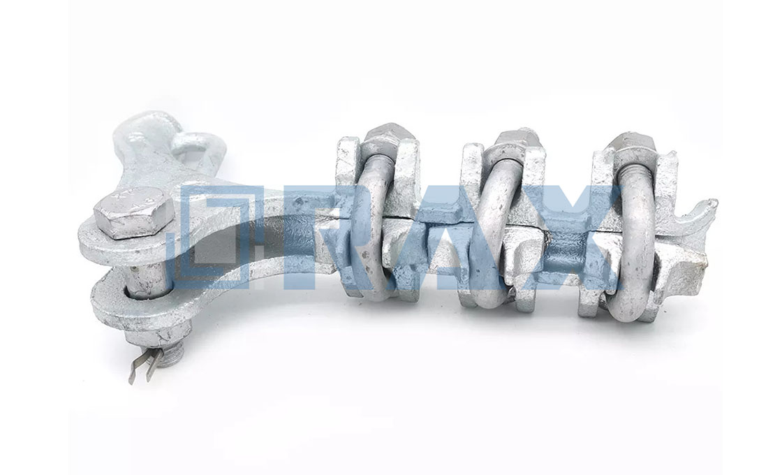
Vergleich von Keil-, Aufhänge- und Pressklemmen
Selbstanspannmechanismus der Keilklemme und Empfindlichkeit gegenüber dem Außendurchmesser
Wedge clamps operate on a tapered mechanical principle where axial tension translates into radial normal force on the conductor. As the line load increases—whether from wind ice or thermal sag—the wedge drives deeper into the grip surface, creating a self-tightening action that resists slippage without requiring external locking mechanisms. This geometric advantage makes them highly effective for dynamic environments where tension fluctuates. However, this same mechanism introduces extreme sensitivity to the Outer Diameter (OD) of the cable being secured.
If the conductor diameter falls outside the specific design range of the wedge, the contact pressure becomes uneven. A mismatch that is too small results in inadequate bite and eventual slip under tension, while an oversized cable can crush the conductor jacket or strands during installation. This OD sensitivity requires precise verification against the conductor specification sheet prior to selection, as generic “one-size-fits-all” assumptions often lead to field failures in variable temperature conditions.
Axialbelastungsgrenzen der Aufhängungsklemme
Suspension clamps are fundamentally designed to support the vertical weight of the conductor and allow longitudinal movement at the tower point, not to terminate high tensile loads. Their internal structure typically utilizes a saddle and shackle assembly that distributes stress evenly around the cable circumference to prevent deformation during low-tension runs. Relying on a standard suspension clamp to handle end-termination tension creates a critical structural mismatch.
The axial load capacity of a suspension clamp is significantly lower than that of a dead-end or anchor clamp. When subjected to significant pulling forces intended for termination, the shear pins or bolts may yield, or the saddle may deform, leading to a catastrophic release of the line. Engineers must strictly distinguish between hardware used for mid-span support versus hardware used for anchoring the line at a corner or dead-end structure; using suspension hardware for tension termination violates basic mechanical integrity principles and voids safety margins defined by IEC standards.
Hydraulische Pressenanforderungen für Pressklemmen
Compression clamps offer the highest holding strength and long-term reliability by permanently deforming a sleeve over the conductor strands to create a cold-welded bond. Unlike the mechanical wedging or bolting methods, this method relies on material flow rather than friction alone. Consequently, the performance of a compression clamp is entirely dependent on the precision of the hydraulic pressing operation during installation.
Successful installation demands a calibrated hydraulic press equipped with dies that exactly match the manufacturer’s specifications for the specific conductor size and clamp model. Using incorrect dies or failing to follow the prescribed press sequence (number of strokes and pressure application points) can result in incomplete crimping, voids within the sleeve, or overheating that anneals the metal and reduces its tensile strength. Once compressed, the connection is irreversible and cannot be adjusted in the field, making the initial tooling setup and operator training a non-negotiable quality control checkpoint for any project involving high-load spans.
| Performance Standard | Grip force >90% of Rated Break Strength (RBS), IEC 120 Compliant | Ensures high safety margins and reliable load bearing |
| Tolerance & QC | ±1mm Precision Tolerance, Dual-Stage Inspection (10-person team) | Guarantees dimensional accuracy and consistent quality control |
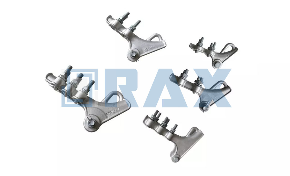
Welche Tragfähigkeit benötigen Sie wirklich?
Maximale Zuglastbewertungen pro Ausführungstyp
Load capacity requirements are strictly defined by the conductor’s Ultimate Tensile Strength (UTS), which serves as the baseline for selecting anchor tension clamps. For overhead lines, dead-end clamps must sustain at least 95% of the conductor UTS to ensure mechanical integrity during extreme weather events or ice loading conditions. Wedge-type grips typically provide a holding force range between 40 kN and 80 kN for distribution voltages, while compression clamps can handle significantly higher loads, often exceeding 160 kN for high-voltage transmission applications involving large ACSR conductors. Manufacturer specifications should be verified against IEC 61284 or ANSI C136 standards to confirm the specific breaking strength rating for the intended cable diameter.
Rutschrisiko-Schwellen unter dynamischen Belastungen
Slippage remains a primary failure mode in tension clamps, occurring when the gripping surface fails to maintain sufficient friction against the conductor strands under varying tension cycles. Industry data suggests that slippage risks become critical when the installed grip retains less than 90% of its original rated holding capacity after dynamic testing. Wedge clamps rely on a self-tightening mechanism where axial load increases contact pressure; however, if the outer diameter (OD) of the conductor is mismatched with the clamp size, the wedge may not seat correctly, leading to gradual strand extrusion or sudden slip. Dynamic load testing per IEC 60889 requires that clamps withstand repeated loading without visible displacement of the conductor within the jaw, ensuring that slippage does not compromise clearance distances over the line’s operational lifespan.
Langzeitdaten zur Durchhangsteuerungsleistung
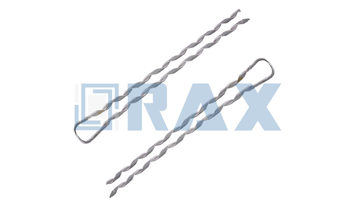
Effective sag control relies on the clamp’s ability to prevent longitudinal movement of the conductor over decades of service, particularly in environments subject to thermal expansion, wind-induced vibration, and galloping. Field studies indicate that properly selected and installed tension clamps exhibit negligible longitudinal creep (<0.5 mm per year) when matched to the correct conductor material and diameter. Preformed helical grips offer superior long-term stability due to their distributed contact stress, reducing localized strand damage compared to single-point wedge designs. Regular inspection intervals should include measurement of any relative displacement between the conductor and clamp body, with replacement recommended if elongation exceeds 1% of the initial grip length to maintain system-wide sag profile consistency.
Materialien, die raue Umgebungen standhalten
Korrosionsrisiken: Aluminiumlegierung vs. Stahl
Material selection in pole line hardware is dictated primarily by the specific environmental conditions of the installation site, particularly regarding corrosion susceptibility and galvanic compatibility with the cable being secured.
Steel offers high tensile strength but remains vulnerable to rust if not properly protected. When used with ADSS cables or aluminum conductors, carbon steel creates a severe galvanic corrosion risk due to the potential difference between the anodic cable and cathodic clamp. This electrochemical reaction accelerates degradation at the contact interface, potentially leading to cable jacket failure or reduced clamp grip integrity over time.
Aluminum alloys, while lighter and naturally resistant to oxidation through passive film formation, present different challenges. In high-salinity environments or acidic soils, aluminum can suffer from pitting corrosion. additionally, direct contact between aluminum clamps and steel bolts without dielectric isolation can induce bimetallic corrosion. The primary advantage of aluminum lies in its compatibility with non-metallic cables like ADSS and OPGW, where it prevents the crushing risks associated with heavier steel fittings and eliminates the need for extensive anti-corrosion coatings on the clamp body itself.
Einfluss der Verzinkungsstandards (ISO 1461)
For steel-based anchor tension clamps, hot-dip galvanizing remains the industry benchmark for long-term environmental protection. Performance is defined by adherence to international coating standards such as ISO 1461, which governs the quality and durability of zinc coatings applied to iron and steel articles.
The standard specifies a minimum mean coating thickness based on substrate weight. For typical heavy-duty hardware, this often translates to an average layer exceeding 85 microns, ensuring Strong resistance against chlorides, moisture, and industrial pollutants. Crucially, the process involves immersion in molten zinc, creating a metallurgical bond that provides superior adhesion compared to paint or powder coating. This bond ensures the protection remains intact even if minor surface scratches occur during handling or installation.
Beyond simple thickness, the microstructure of the galvanized layer matters. A smooth, bright finish indicates proper fluxing and dipping temperatures, minimizing roughness that could stress the cable sheath. Conversely, excessive spangle formation or uneven coverage may indicate processing deviations that compromise uniformity in harsh coastal or chemical exposure zones. Verification via SGS testing or similar third-party audits confirms that the zinc alloy composition meets specification, preventing premature zinc depletion and subsequent steel exposure.
Effekte thermischer Zyklen auf die Momentenhaftung
Anchor tension clamps installed in regions experiencing significant temperature fluctuations must account for thermal cycling effects on bolted joint integrity. As ambient temperatures swing between extremes—such as sub-zero nights and scorching days—the differential expansion rates between the clamp material, the fasteners, and the supported cable can lead to loosening or increased bearing pressure.
In steel-clamp assemblies with steel bolts, coefficients of thermal expansion are relatively similar, reducing internal stress. However, when combining dissimilar materials—for instance, an aluminum clamp with steel bolts—the mismatch can cause cyclic shear stress at the thread interface. Over time, this fatigue may reduce preload torque, increasing slippage risk under dynamic wind or ice loading conditions.
To mitigate this, manufacturers often employ locking mechanisms such as serrated flange nuts, thread-locking compounds, or double-nut configurations. Additionally, pre-tensioning procedures should allow for controlled seating after initial tightening to compensate for minor embedment relaxation caused by surface irregularities settling under load. Regular inspection intervals following extreme weather events help verify that torque values remain within acceptable operational thresholds without requiring full disassembly.

Welche Klemme passt am besten zu Ihrer Anwendung?
Selecting the correct anchor tension clamp requires matching mechanical loads to cable geometry while minimizing jacket damage risks and long-term maintenance costs.
Anforderungen an den ADSS/OPGW-Mantelschutz
When installing ADSS or OPGW fiber optic cables, the primary concern is preventing micro-cracks in the polymer jacket caused by localized pressure points. Unlike standard power conductors which tolerate higher surface stress, optical fibers are sensitive to bending radius violations and point loading. Using a wedge-type clamp on ADSS without proper helical groove alignment can create stress concentrations that lead to water ingress along the cable core over time, compromising signal integrity and accelerating corrosion of internal strength members. The recommended approach involves preformed helical grips designed to distribute clamping force evenly across the entire circumference, ensuring the jacket remains intact even under dynamic wind-induced vibration cycles.
Sicherheitsanforderungen bei hochspannweiten Flussquerungen
River crossings present unique engineering challenges due to increased sag spans, heavier ice loading conditions, and greater exposure to corrosive moisture environments. In these scenarios, dead-end tension clamps must accommodate both high static tensile loads and cyclic fatigue from thermal expansion and contraction. Bolted designs offer field-adjustability but require precise torque application to maintain consistent grip pressure; failure to do so results in slippage during extreme weather events that may cause pole collapse. Conversely, compression-type termination sleeves provide superior slip resistance but demand hydraulic presses unavailable at remote sites—a critical logistical consideration when selecting hardware for trans-river installations where service access is limited.</p
Auswirkungen auf die Wartungskosten von FTTH-Leitungen
structures are required to manage these dynamic loads, so the durability and reliability of the chosen hardware become critical factors in controlling FTTH maintenance costs.
| Klammertyp | Primary Application | Technical Standards (Rax Power) | Operational Benefit |
|---|---|---|---|
| Preformed Guy Grips | Anchoring stay wires and guys on overhead lines | Grip force exceeding 90% of conductor break strength; ISO 1461 galvanizing >85μm coating | Uniform stress distribution prevents local cable damage; ensures zero slippage over the line lifespan |
| ADSS/OPGW Suspension Clamps | Supporting fiber optic cables on tangent poles and towers | Hot-forged components with protective rubber inserts; IEC 120 gauge tested | Vibration dampening protects optical fibers; maintains clearance by controlling creep and sag |
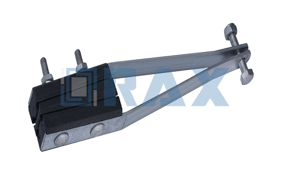
| Dead-End Tension Clamps | Terminating conductors at high tension angles or dead-end structures | Wedge or helical design; SGS verified; rigorous dual-stage QC inspection | Superior slip resistance for high-voltage stability; simplifies installation with no special tools required |
| Bolted Pole Bands & Racks | Mounting insulators, transformers, and equipment to utility poles | Automated production with ±1mm tolerance; ISO 1461-compliant hot-dip galvanizing | High dimensional accuracy ensures secure fit; robust strength for long-term equipment support |
Verhinderung häufiger Klemmenfehler
Verhinderung galvanischer Korrosion an Verankerungen
Galvanic corrosion is the primary cause of premature anchor failure. It occurs when dissimilar metals are electrically connected in the presence of an electrolyte, triggering a rapid degradation of the anodic material.
In overhead line applications, the risk is highest when steel anchors or carbon steel clamps come into direct contact with aluminum conductors, copper grounding wires, or even dissimilar stainless steel components. Moisture acts as the electrolyte, causing the more anodic metal (typically the steel anchor) to corrode sacrificially. This corrosion is insidious; it begins at the microscopic level and rapidly compromises the structural integrity of the anchor, leading to catastrophic pull-out failures under load.
To mitigate this, engineers must prioritize isolation or compatible material pairing. While isolation tapes and bimetallic washers are effective field remedies, the foundation of corrosion resistance lies in the base material treatment. We strictly adhere to ISO 1461 hot-dip galvanizing standards for all our steel anchor products. This process creates a metallurgical bond that provides a sacrificial layer far superior to electro-plating. Crucially, we ensure a mean coating thickness exceeding 85 microns. This heavy-duty barrier is essential for long-term durability, particularly in the aggressive coastal or industrial environments often found in our South American and Russian export markets.
- Material Compatibility: Always verify the galvanic potential between the anchor body and the connected hardware. Use bimetallic interfaces when connecting copper to steel.
- Coating Integrity: Inspect for coating damage during installation. Any scratch exposing the base steel becomes a focal point for corrosion.
- Sacrificial Protection: Ensure galvanized coatings meet the >85 micron threshold to provide adequate sacrificial material over the asset’s 20-30 year lifecycle.
Techniken zur Minderung vibrationsbedingter Lockerung
Aeolian vibration—the wind-induced oscillation of conductors—is a constant threat to the mechanical stability of pole line hardware. This constant, low-amplitude vibration works nuts loose and creates fretting wear between contacting surfaces. Over time, this leads to a loss of clamping force, allowing the conductor to slip or the hardware to detach from the pole entirely.
Mitigation requires a dual approach: proper locking mechanisms in the field and precision manufacturing in the factory. We have found that the root cause of many field failures is poor dimensional fit. If the tolerance between the bolt and the clamp body is too loose, vibration creates a “rattle” effect that accelerates loosening. Our automated production lines enforce a strict ±1mm tolerance on all critical dimensions. This precision ensures a snug, interference-free fit that eliminates the play required for vibration to initiate loosening. Furthermore, the use of preformed line products like spiral vibration dampers can absorb energy before it reaches the anchor clamp, protecting the hardware connection from fatigue.
Einfluss der Oberflächenbeschaffenheit auf die Klemmenlebensdauer
The aesthetic appeal of a clamp is secondary to the functional quality of its surface finish. A rough, uneven, or thin coating is a magnet for environmental contaminants that trap moisture against the base metal, accelerating under-film corrosion. In contrast, a smooth, uniform finish sheds water and debris, extending the service life of the hardware significantly.
Hot-dip galvanizing is the industry standard for steel components, but the *quality* of that dip varies wildly. Many low-cost manufacturers utilize cold-galvanizing (spray zinc) which offers negligible long-term protection. We utilize a leading hot-dip galvanizing technology that results in a smooth, bright finish free from drips and slag buildup. This is not just cosmetic; a smoother surface reduces friction during installation and prevents stress concentrations that could lead to cracking. Our dedicated 10-person QC team monitors every batch, checking for coating continuity via gauge testing per IEC 120 standards. We ensure that 100% of products undergo a double-review process before packaging, guaranteeing that the surface integrity required for 25+ years of service is present on every single unit shipped.
- Coating Thickness: Verify mean thickness exceeds 85 microns (ISO 1461) to ensure adequate zinc reservoir for self-healing minor scratches.
- Surface Uniformity: Reject hardware with rough surfaces or zinc nodules, as these create initiation points for corrosion cracking.
- Third-Party Validation: Rely on SGS-verified coatings to ensure the chemical composition of the zinc alloy provides optimal corrosion resistance.
Fazit
Your project requires matching clamp load ratings to specific environmental and mechanical demands without overspecifying cost. Wedge clamps suit dry, stable spans where self-tightening mechanisms reduce maintenance, but compression clamps deliver superior grip for high-vibration corridors or river crossings where slip thresholds threaten cable integrity. We focus on ISO 1461 galvanizing standards because they prevent corrosion failures in coastal or industrial zones—this isn’t optional for long-term reliability. Our engineers prioritize torque retention under thermal cycling since loosened anchors cause immediate slippage risks under dynamic wind loads.
In contrast to wedge clamps, anchor tension clamps are specifically designed for securing the ends of conductors or cables, transferring mechanical load to supporting structures while preventing slippage under high tension and maintaining electrical integrity.
While wedge clamps excel in stable, dry environments, anchor tension clamps serve a distinct purpose by securing cable ends and transferring mechanical loads to supporting structures.
Häufig gestellte Fragen
Was ist ein Anker-Spannclip?
Eine Ankerspannvorrichtung sichert das Ende eines Leiters oder Kabels und leitet die mechanische Belastung auf die Tragkonstruktion ab. Sie verhindert ein Durchrutschen unter hoher Zugspannung und gewährleistet dabei die elektrische Integrität.
Was sind die wichtigsten Arten von verwendeten Spannklammern?
Zu den gängigen Typen gehören geschraubte, Keil-, vorgeformte und Pressklemmen. Jede bietet deutliche Vorteile in Abhängigkeit von der Installationsmethode, dem Leitertyp und den Umgebungsbedingungen.
Was ist der Unterschied zwischen Anker- und Endklemmen?
Ankerspannverschlüsse dienen der Sicherung von Leitern an Leitungsenden oder Übergangsstellen, während Abspannverschlüsse Kabel unter voller Spannung absetzen. Beide verhindern ein Durchrutschen, unterscheiden sich jedoch im Anwendungskontext und in der Lastverteilung.
Wann sollten Schraubenklemmen gegenüber Keilklemmen verwendet werden?
Verschraubte Klemmen eignen sich ideal für häufige Wartungsarbeiten oder variable Lasten, während Keilklemmen für permanente Installationen mit konstanter Spannung geeignet sind. Die Wahl hängt von der Zugänglichkeit, der Laststabilität und den Serviceanforderungen ab.
Können Ankerklammern in Küstenregionen verwendet werden?
Ja, sofern sie aus korrosionsbeständigen Materialien wie Edelstahl oder heißverzinktem Stahl hergestellt sind. Eine ordnungsgemäße Abdichtung und Wartung verlängert die Lebensdauer in salzhaltigen Umgebungen.